For pump systems to last many years with reliable operation, it is critical to get key design areas right. A poorly designed pump system will generate decades of high maintenance and poor reliability for the operators. Once in place, the only fix for design errors is a redesign of the pump and system. This article discusses five areas where design mistakes are common.
1. Missed operating point
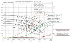
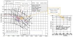
When a pump system is designed, the primary function of the pump operation gets the focus, yet oftentimes, there are secondary functions as part of the system that will put different conditions on the pump. For an example: A dilution pump supplied dilution water to the process but also served to fill a water tank particularly on startup. The startup condition was never included in part of the pump and system design. This led to the pump operating off the curve for the secondary operating point, causing significant cavitation. As a consequence, the pump suffered pump casing failures from the cavitation of the secondary operating point, which only occurred a small amount of the time. The fix was to install a fixed orifice on the water tank fill line. The different operating points can be seen in the pump and system curves in Figure 1. The second system curve needed more friction head to put the additional operating point in a reliable point.2. Air entrainment
If a process such as paper stock operates with air entrainment, some pump sizing adjustments may be necessary. Many pumps can handle up to 2% air without any adjustments for performance losses; however, if air entrainment exceeds 2% air, corrections will often need to be made. When air entrainment approaches 4% to 6%, up to 30% to 40% of pump capacity may be lost. A larger impeller can oftentimes help offset the reduction in pump performance with air. The motor will also need to be sized for the pump as if no air was present, which will increase brake horsepower (BHP).
Air entrainment can enter the pump fluid in several ways, such as pipes dumping into a tank and splashing and inducing air into the fluid or through suction vortex. The suction bringing in air is partly addressed by having proper pump submergence. This should be known for any pump system design and even process controls to prevent the tank level from reaching below this minimum level to satisfy pump submergence. If tank level must drop below minimum submergence for some reason, a vortex breaker may need to be installed in the pump suction design of the tank. Pump suction lines into tanks should have elbows turned down with proper spacing to prevent vortex and proper fluid supply into the suction pipe. Suction lines straight into tanks will require a higher tank level to prevent vortex conditions. Pump submergence can be calculated by the following equation:
S = D + 0.574*Q/D^1.5
Where:
Q is flow in gpm
D is suction pipe diameter in inches
S is submergence in inches of fluid level above suction
3. Miscalculating system head
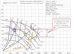
Errors in system head design calculations and BHP can lead to problems under certain process conditions. This can happen in several ways such as not having the correct viscosity or specific gravity of the fluid being pumped. These will affect the friction head and BHP calculations. When pumping paper stock in the pulp and paper industry, the consistency will greatly change the system curve. Up to 2% consistency and system head is similar to water, but over 2% consistency and significant increase in system head will alter pump sizing.
The pump and system curves in Figure 3 show how the pump performance is affected by pumping different consistencies. The higher friction head from higher consistency stock moves the system curve up the pump curve. When the consistency and system curve is not calculated, the pump will not meet the performance needs. Higher consistency stock also has a slightly higher specific gravity.4. Material specifications
Material specifications can often be overlooked on the front end of pump selection due to cost or under-estimating the fluid conditions. The application may include a corrosive application or pumping an abrasive material. In that case, a cast iron casing is probably not the best choice for that type of application. A stainless alloy (316, CD4) may be a better choice for corrosion applications. Abrasive applications may benefit from a hardened stainless steel (CD4 or 17-4PH) or high chrome iron up to 600 Bhn.
Component material selection may also depend on pump design. If the pump is running packing, a hardened shaft sleeve should be specified, but if a mechanical seal is used, a standard sleeve may be used.
Several factors will make the pumped fluid more abrasive such as higher hardness of abrasive material, higher quantities of particles and larger-size particles. Higher speed pumps and higher pump heads also increase wear potential. Hard coatings may work well on low-impact angle situations.
5. Pump suction design
So much of poor pump reliability can be traced back to the pump suction design conditions. If the fluid does not reach the pump impeller eye, the pump cannot do any work on the fluid to increase its energy (flow or head). The suction conditions should be such that the fluid filling the eye of the impeller is at a sufficient pressure so that it remains in liquid phase as it travels through the pump.
The pump suction design must satisfy the net positive suction head required (NPSHR) for the pump. Many times, this is misapplied or not investigated enough in the system design or pump selection phase of a project. The pump curve does not really give NPSHR, but NPSH3, which means the pump is already cavitating and has lost 3% of head. An NPSHmargin must be applied for most pump applications to prevent significant cavitation from affecting pump performance. NPSHmargin is typically between 1.2 and 2.5 to satisfy most applications. Suction energy can be an indicator of how much NPSHmargin is needed. Higher suction energy requires higher NPSHmargin.
NPSHR = NPSH3*NPSHmargin
The net positive suction head available (NPSHA) is the other side of the suction equation to evaluate in a pump system design. The equation for NPSHA is:
NPSHA = Hs – Hf – Hv + Hatm
Where:
Hs is suction head in feet
Hf is suction friction loss in feet
Hv is vapor pressure in feet
Hatm is atmospheric pressure in feet
NPSHA is an absolute pressure (head) so atmospheric pressure is a key factor. A pump in Denver, Colorado, will have a different NPSHA than the same system in Kossuth, Mississippi. Vapor pressure is another important factor that is highly dependent on fluid temperature and fluid type.
Suction piping must be designed such that suction friction losses are kept to a minimum. Suction piping should be sized so that suction line velocities are in the 4 to 7 ft/s range. The pump suction should also have a sufficient amount of straight run into the pump. Typically, this will be 5 to 10 times the suction pipe diameter. Straight run is not just to minimize friction loss but to establish a straight fluid path and uniform velocity entering the pump suction. Do not install a valve directly on the pump suction, but upstream in the straight run section of piping.
NPSHA must be greater than NPSHR if the pump is to operate without any significant cavitation. If a pump operates to the right of best efficiency point (BEP) — like the pump in Figure 1 at a second operating point — then a much higher NPSHA will be required.
These design oversights will negatively affect pump reliability for every year the pump system is operating until they are corrected. While most of these can be addressed, rooting this out up-front in the design phase is the most cost-effective time to do it. Give these areas a critical look before your next pump system is installed and started up.
Randy Riddell, CMRP, PSAP, CLS, is the reliability manager for Essity at the Barton Mill in Alabama. He has over 30 years of industrial experience with a career focus on equipment reliability. Riddell has a Bachelor of Science in mechanical engineering from Mississippi State University. He is a certified maintenance and reliability professional from the Society of Maintenance & Reliability Professionals, and he has a pump system assessment professional (PSAP) certificate from the Hydraulic Institute. Riddell can be reached at [email protected].
