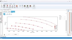
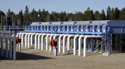
The compressor control system plays a crucial role in the operation, performance and reliability of any compressor train. This is a key tool to manage gas flows, minimizing upsets and keeping gas movements at satisfactory levels with eyes on compressor safety, monitoring and efficiency. The compressor control system is a key component for improving a compressor’s ability to handle transients and disturbances, to continue the compression of gas for years without any shutdown and to operate at a desired operating range.
This article describes the latest improvements, useful guidelines and practical notes on compressor control systems to ensure that compressors can be operated safely, reliably and efficiently. The article also discusses details on flow management and capacity control solutions for compressors.
Variable speed
The speed variation is recognized as the best method of the overall control and capacity or flow control of nearly all compressor types. The variable speed has many advantages for compressor control. For most compressor applications, variable-speed control is the premier choice. High part-load efficiencies can usually be achieved by speed variation. Most often, part-load efficiencies are more than 90% of the rated efficiency. Using variable speed, a turbo-compressor only produces the head necessary in the part-load operation. There is a possibility to overload the downstream system, for instance, by volume flow, because of overspeed, which requires care for some compressor systems. Particularly, steam turbine or gas turbine-driven compressors could face overspeed. Therefore, control systems should properly manage the operation and avoid such cases.
Suction throttling
A suction throttling valve — a control valve at suction — can be used for compressor control. Such a control method is often suitable to many compressor types. It is a simple and low-cost tool that can offer some flexibilities. A suction throttling valve installed at the suction side of a compressor is usually so widely accepted that it might be regarded as an integral part of the compressor package for some compressor models, such as some small-size integrally geared compressors. In this way, the performance map for a compressor using a suction throttling valve could be prepared with the operation of such valve as a parameter incorporated in the compressor map.
Inlet guide vanes
Adjustment of inlet guide vanes (IGV), or sometimes referred to as the variable IGV, is an effective control method for turbo-compressors. Adjustment of IGV is a real compressor head variation as opposed to suction throttling. According to turbo-compressor’s performance equations, the head is a function of the peripheral gas velocity at the stage inlet (impeller inlet or axial stage inlet). By adjusting the IGV, the incidence angle at the impeller inlet can be altered, thus changing the peripheral velocity. An important property of IGVs is that only the pertaining impeller performance is influenced. In principle, guide vanes can be inserted at the inlet of each stage — each impeller or each axial compressor stage — but due to lack of space or other difficulties and issues, multistage compressors are normally only equipped with one or two set of IGVs. For integrally geared compressors, more space is often available since each 3D impeller is installed separately on the main casing. Hence, more IGVs can be installed for such compressors. Based on experience, most integrally geared compressors have the first stage or the first and second stage equipped with IGV. Too often, only the first stage IGV is automatically controlled, and the second stage is only adjusted manually. However, there are other options and configurations.
The situation is similar for axial compressors as it is theoretically possible to install variable IGV for all stages, and there have been some axial compressors using variable IGV for all stages, but usually a few stages are equipped with variable IGVs.
Medium part-load efficiencies have been reported for adjustment of IGV. This is typically lower than variable-speed method, but higher than suction throttling. Many compressors such as integrally geared centrifugal compressors cannot be variable-speed machines because of their complex dynamics. Then, the adjustment of IGV is the best control method that can be used for those compressors.
In some other compressor types, such as axial compressors or conventional-type centrifugal compressors, both variable speed and IGV can be used to offer good flexibility and control capabilities. With negative pre-rotation of the IGVs, it might theoretically be possible to overload a compressor. Such a negative pre-rotation of IGVs could be used in high capacity or high-pressure cases — higher than rated ones — where the efficiency is usually lower than the best efficiency point (BEP). Such a relatively inefficient operation might only be useful for some short time-transient cases. Practically, the chance of overloading is small.
Trends in using IGVs
There are two different trends in the turbo-compressor industry regarding the IGV. The first trend is to use variable IGV in more stages of integrally geared centrifugal compressors and axial compressor. In this way, such compressors can offer better flexibility and control capabilities. Another trend is toward limiting the IGV applications to absolute minimum due to reliability and operational concerns. Adjustable (or variable) IGV systems are expensive and complicated mechanisms, which could offer mechanical complexity and some reliability issues. Supporters of each view have their own reasons and justifications, and it is generally difficult to give a general rule regarding adjustable IGV systems. The author’s recommendation is that any adjustable IGV system is an expensive and complex system that should only be used after a thorough review and proper reference checks. Such a system should only be used where needed, and it should be employed with great care. If used, a high-quality system with proper design and items from reputable suppliers should be employed.
Bypass/recycle
Another compressor control tool is the bypass (or recycle). The gas flow is bypassed from the compressor discharge to the compressor suction through a sophisticated control valve. This is a simple control method that can be used for all compressor types, but it is an inefficient and wasteful method that should be used as the last means of control. The high energy cost at part-load should carefully be highlighted when using bypass (or recycle), and then it is usually used as a backup tool and for short periods of time, often transient situations such as startup or shutdown.
Traditional and old-fashioned control systems
The traditional control system approach was typically based on separate hardware to handle different functions in a compressor-driver train. For instance, for turbine-driven compressors, the old-fashioned control configuration was a separate turbine controller to operate the driver and its auxiliaries, and often, separate controllers were used for anti-surge system, load sharing, etc. All of these features have been highly interactive and have needed to work harmoniously to meet the gas movement plant specification and facility requirements in all operating cases. In such traditional control systems, each controller often uses a different programming language and user interface. The noncorrelated actions of the driver and compressor controls in old systems can adversely affect the overall operation and diminish the overall compressor train efficiency.
Modern compressor train control integration
The integrated driver and compressor control system eliminates the need for independent controllers, thereby eliminating the problems highlighted for traditional and old-fashioned systems. In addition, an integrated control system results in fewer control components and spare parts, and simplifies overall operation. The integrated compressor train system is able to handle all the required algorithms in a single controller, plus a dedicated anti-surge and anti-choke controller.
All control algorithms should ideally be installed in a single environment, and they are developed using only one programming language, reducing system errors and minimizing maintenance and future upgrading tasks. Moreover, operators deal with a single interface to monitor the driver, compressor, associated auxiliaries and the surrounding process by simply switching from one graphic video page to another.
Central coordinated control
The key approach to modern compressor control system is to use a central system. This is applicable to all multi-agent control systems for variable-geometry compressors such as centrifugal compressors using IGVs, integrally geared centrifugal compressors or advanced axial compressors. The first step is to identify the constituent agents of the compressor control system. Then, all should be incorporated in a central and integral control system.
Some engineers have indicated some agents or subsystems that can function autonomously. There have been compressors with control systems of independent control loops. Such an independent operation could result in instability. Different agents operated independently can interact with each other and cause instability and fluctuations. Also, many control goals require the action of more than one agent. In other words, all agents should be linked properly and operated or coordinated by a single control system.
Dynamic decoupling
A compression system consists of multiple control loops that all have the purpose of keeping certain operating parameters, such as flow, pressure, temperatures, etc., at or close to predefined set points. In some situations, these control loops can interact to give unwanted operational oscillations or even situations where the system is pushed to the extremes or outside of its boundaries. In those cases, the interacting control loops need to be decoupled.
It is difficult to predict which control loops are dynamically coupled. However, systems with low capacitance and with fast responding control loops are more prone to be dynamically coupled.
Decoupling of interacting control loops can be done by application of loop controller tuning. However, this is usually not desired because it leads to a decrease in efficiency and overall performance. Thus, decoupling action normally consist of having the controllers that are interacting monitor and compensate for each other’s output. Thereby, the loop interactions will be dynamically decoupled. This can be verified by extensive simulations before the real-world application.
The best consideration to avoid coupling and achieve decoupling is that all control loops and all sensors and actuators should be linked properly and operated or coordinated by a single control system; in this way, the chance of interaction is very low.
Compressor control and dynamic simulations
Special attention should be given to the dynamic modeling and simulations of any compressor unit with all its compressor and associated facilities to evaluate the performance of the control system and to properly set up the compressor control system. The dynamic model should specifically be used to investigate the performance compressors at all possible rated and off-rated conditions. In other words, all possible risks and abnormal situations should be identified and included in the simulation and see how the compressor control system reacts to them.
For example, one important case is how the compressor and its control system might react to low flow cases. Another important point is the limit of a load-sharing system; since, in some extreme situations — for instance, very low flow — it might not be possible to share the compression load between the parallel coupled compressors.
The dynamic simulations should be used to investigate how a compressor system will respond to changes in the suction conditions such as inlet gas composition.
The compressor operation should be adjusted by proper prediction of plant behavior, particularly its downstream and upstream facilities. Model-based approach can be used for the compressor control. Such a model-based approach can also provide possibilities for control software testing and verification through real-time simulation.
Amin Almasi is a lead mechanical engineer in Australia. He is a chartered professional engineer of Engineers Australia (MIEAust CPEng – Mechanical) and IMechE (CEng MIMechE) in addition to a M.Sc. and B.Sc. in mechanical engineering and RPEQ (Registered Professional Engineer in Queensland). He specializes in mechanical equipment and machineries including centrifugal, screw and reciprocating compressors, gas turbines, steam turbines, engines, pumps, condition monitoring, reliability, as well as fire protection, power generation, water treatment, material handling and others. Almasi is an active member of Engineers Australia, IMechE, ASME and SPE. He has authored more than 150 papers and articles dealing with rotating equipment, condition monitoring, fire protection, power generation, water treatment, material handling and reliability. He can be reached at [email protected].


