Laminar flow
It has been shown that, under certain conditions, turbulence in fluids can be minimized, leading to laminar flow. Thankfully, laminar flow does not require supercooling. However, it has proven difficult to realize the benefits of laminar flow in fluid control valves due to the necessary design restrictions (such as obstructions, barriers and edges) required for operation. Consequently, laminar flow is primarily observed in pipes and linear stretches of flow, not in valves. The practical problem has been to sustain laminar characteristics while achieving full control. But turbulence always seems to occur. Therefore, the development of practicable nonturbulent fluid control devices has been elusive — until recently.
If there were a way to induce fluids to act as if there were no resistance — as if nothing were in the way, as if turbulence did not exist — immense practical benefits might be achieved. If pressures and flows could be influenced in an instant without pressure spikes and interactive systems effects, if fluid control devices could be substantially reduced in size, if noise and vibration could be reduced, and if device activation could be achieved with minimal force, benefits would be significant.
Thirty years ago, a laminar flow valve design was developed to enhance the efficiency of car wash operations. However, it went almost entirely unnoticed as knowledge and dissemination of the technology was stifled, initially by lack of vision and later by a combination of technology-driven strategy, mismanagement and other failings.
The good news is that a laminar flow valve technology exists that can solve a wide variety of fluid control problems, yet industry structure and lack of resources continue to constrain widespread implementation. The following outlines the critical elements and properties of this groundbreaking technology.
Turbulence: The bane of fluid control
Turbulence in a valve causes a variety of negative effects such as cavitation, K factor head loss, noise, vibration, imprecise control and excessive wear. Cavitation is particularly troublesome in some fluids such as water. Water contains dissolved gases, which, when accelerated through a constriction, form small bubbles that implode with enough force to cause minute bits of metal to be dislodged from the edge of valve seats and housings. In time, enough metal erodes from the valve surfaces that the device begins to leak, and control properties (ability to precisely regulate flow and/or pressure) are diminished. Eventually, the valves must be reconditioned or replaced. In high performance applications, this may require the expensive interruption of important processes (e.g., hydraulic applications, chemical processes or oil and gas extraction/processing). Turbulence also causes noise and vibration that increase over time as valve integrity deteriorates. Precision applications requiring quiet operation and accuracy are greatly disrupted by excessive noise and vibration. Consequently, these inefficiencies drive valve designs to be larger and less effective than they should be if turbulence did not enter the equation. Turbulence can nearly be eliminated from the valve equation by using two cylindrical, parallel flat plates.
How flat-plate devices work
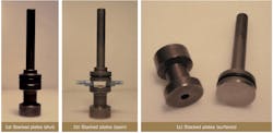
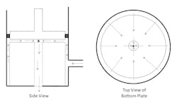
Most valve designs are some version of a plug in a hole or a barrier across an opening that inevitably introduce turbulence. The resulting negative consequences are extremely difficult to ameliorate. The flat-plate technology uses a unique internal topology to generate laminar flow within the device, thus nearly eliminating most of the unwanted effects. The basic design consists of two parallel flat plates (as shown in Figure 2).After entering the device through the input orifice, fluid rises around the outside of the cylindrical bottom plate. When it reaches the top edge of the plate, the resistance of the cylinder itself disappears, and the fluid shoots across the plate from the entire circumference. The flow collides in the center from all directions. An outlet orifice (hole) is cut in the center of the bottom plate directly below the fluid collision. Fluid exits the device down this orifice. The end result is fluid flow through the device with no turbulence along the plate surfaces, resulting in superior operation and control.
When the plates are pushed together, the flow stops. When the plates are pulled apart, laminar flow occurs across the plate surfaces. Any turbulence occurring before reaching the edge of the plates or after the central collision is inconsequential to the operation of the device. It may be difficult to believe that this circuitous route through the valve results in laminar flow — but it does.
As illustrated in Figure 2, the basic topology of flat-plate devices is radically different from other fluid control (valve) designs. It must be noted that these devices are not devoid of turbulence; instead, they manage turbulence so that it occurs in only noncritical areas at input and output. At input, fluid slows so that it can be fed evenly to the operational surfaces (parallel plates). After passing between the two plates and colliding in the center, the resulting fluid collision is constrained by the top plate and forced to occur within the output orifice where the effects of turbulence are noncritical for control purposes and are damped within the output orifice and by the fluid-to-fluid collision itself before exiting the device.
Properties of flat-plate devices
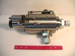
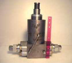
Flat-plate valve prototypes with throughputs ranging from a few ounces per minute to 1,200 gallons per minute (gpm) have been built and tested. The most interesting operational prototypes (control and relief valves) are rated at up to 200 gpm at between 5,000 and 6,000 pounds per square inch (psi). They are surprisingly compact at 14 to 18 inches tall and weigh between 50 and 80 pounds (lbs).
Interestingly, what happens in the center of these devices is not well understood. The operational surfaces of the flat plates are only a few inches in diameter. When operating fully open, the average speed of fluid across those surfaces is several hundred miles per hour. The fluid accelerates from a modest speed when it begins its journey across the plates to its maximum at the point of the center collision — perhaps well over a thousand miles per hour. No erosion has ever been observed on the surfaces of the plates. Clearly, laminar flow is occurring here, producing some jaw-dropping measurements.
Another critical design element is the narrow separation between the plates. To open or close these devices, the top plate needs to move only a fraction of an inch. Therefore, actuation from fully open to fully closed (or vice versa) is extremely fast, resulting in near instantaneous activation with minuscule pressure spikes.
This technology has the potential to rewrite the book on fluid control. It is also important to consider the applications that may take advantage of the curious phenomenon occurring in the center of these devices — the fluid-to-fluid collision at immense speeds. This phenomenon occurs in devices that were designed for fluid control, not maximum fluid speed. Some observers familiar with this technology have speculated that devices might be designed to amplify that speed severalfold, making possible applications to sterilize water mechanically, create new chemicals, alter molecular bonds or improve water saws, for example. These possibilities are speculative and untested. Yet, there is something previously unknown and poorly understood happening in the interior of these valves.
Where has this technology been?
The original inventor developed the earliest version of this technology to control water and chemicals for car washes. The technology allowed 12 bays to be handled on one water line, whereas the previous systems could only handle four bays. The inventor formed his first company to manufacture and market these valves. However, over the objection of the inventor, the valves were reengineered to be only marginally better than existing valves to accommodate a poor business model by management. The company subsequently resisted further technological innovation. In the ensuing years, the inventor made two more attempts to develop and market advanced versions of the technology.
The inventor’s third company developed an even more sophisticated version of the technology that is balanced for both upstream and downstream conditions. The existing prototype is a control valve rated at 200 gpm at 6,000 psi (see Figure 4). This advanced technology allows devices to be actuated with very small forces (a few ounces) against very large pressures (greater than 6,000 psi). The device is only 17 inches tall, 5.5 inches in diameter, and weighs approximately 80 lbs. By the time this device was perfected, the inventor was in his 80s and was unable to attract serious capital for another attempt at commercialization.
Conclusion
This sophisticated technology has the potential to alter the landscape in fluid control, which would be a considerable contribution to industry if it is widely available. It also has the ability to improve efficiencies and enhance industrial processes. Additionally, the technology’s properties of laminar flow combined with blazing fluid speed could have significant applications in new directions beyond fluid control.
Authors’ note: Thomas Christensen, co-inventor of the full-balance technology, has been part of a group led by Barth Strempek who, following the passing of the original inventor, spent several years reassembling the pieces of this technology (prototypes, patents, designs, files, etc.). These pieces had been dispersed among various entities.
R. Barth Strempek, Ph.D., holds an undergraduate civil engineering degree from MIT, a Master of Business Administration (MBA) from Harvard, and a doctorate in strategic management from Virginia Tech. His career began as a transportation engineer at Parsons, Brinckerhoff, Quade and Douglas in NYC and later at Conrail, R. L. Banks, & Assoc., Informatics General Corporation, and CSX Corporation as director of corporate planning. Dr. Strempek taught at Radford University, Virginia Tech, and Elon University where he was named the first Doherty Professor of Entrepreneurial Leadership and was awarded emeritus status upon his retirement in 2017. He can be reached at [email protected] or 919-356-1226.
Thomas Christensen holds undergraduate and graduate degrees in agricultural engineering from the University of Maine. In his early career, he worked as a research engineer for Caterpillar Tractor Co. Upon returning to the University of Maine, he spent 40 years teaching engineering and conducting fluid power and machine development research until his retirement in 2013, when he was awarded emeritus status. Christensen also worked as the company engineer for an industrial fluid power supply company for 14 years and was a licensed PE for over 38 years. He can be reached at 207-299-4334 or [email protected].
