Control valves have drawn more and more attention in recent years, and modern diagnostic technologies and techniques are helping them shine under this increased scrutiny.
For many years, end-users focused on infrastructure-related assets, invested in advanced process control system equipment, and, following the tragedy of 9/11, tightened plant security. Meanwhile, control valves, while essential, were line items buried in the maintenance budget.
The script is different today, however, thanks to global competition and growing pressure to increase profits, boost plant performance, and improve process reliability. The final control element has a direct impact on a facility’s operational excellence – a combination of profitability, plant efficiency, quality, and safety – putting it squarely on the radar screens of maintenance teams and reliability and process control engineers.
This, in turn, has made valve diagnostics more important than ever. To keep a plant’s control valves performing optimally, the end-user must be able to monitor each valve’s performance and have actionable information to use in identifying which valves require maintenance, accurately diagnosing valve problems, and planning maintenance activities. And they need to have this information in hand before valve problems impact process performance.
Diagnostic methodologies and technologies for control valves have evolved greatly in the past 20 years with the advent of microprocessor-based valve positioners and the introduction of user-friendly ways to integrate the information into the supervisory system. This article will review the milestones in this evolution and describe how online valve diagnostics (OVD) can help improve process integrity by giving operations personnel the information they need to address problems early, before they become major issues. It also will discuss the various types of diagnostic information that can be provided by digital valve positioners and explain how to integrate this information with a plant asset management solution.
Valve Diagnostics Timeline: Pre-1980
Prior to the 1980s, control valves could not be monitored remotely and diagnosing a problem valve involved the use of mechanical tools and techniques that could only be mastered through extensive hands-on experience.
It was not uncommon to see a technician apply a finger to a valve stem to “feel” the motion of the valve. This technique was, certainly, more of an art than a science. Determining whether the motion of the valve was “normal” required a unique skill set and significant experience. And unless the valve’s motion was jerky (sticking and slipping), this technique provided no clues as to what might be wrong with the valve.
Veteran technicians also will recall using pencil and paper to record pressure readings from the gauge on a valve’s actuator and valve positions from a dial caliper. These readings would then be used to calculate friction and spring range.
Valve Diagnostics Timeline: 1980s
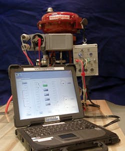
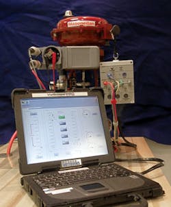
The 1980s saw the introduction of computers and portable data acquisition systems into process control facilities. These portable systems (Figure 1) used external sensors to measure the forces generated by a valve’s actuator and used a travel sensor to measure the valve’s motion. It was the birth of the valve signature concept.
These portable valve diagnostic tools were (and still are) highly effective for validating the health of a control valve before putting it in service or for verifying a valve’s condition post-repair. They also are still successfully used to diagnose the health of control valves equipped with analog positioners.
These tools are not, however, user-friendly. The diagnostic process is time-consuming, taking at least one hour per valve. Personnel must be specially trained in installing the sensors. Analyzing the data so that it becomes actionable information involves significant number-crunching. Personnel may be required to enter potentially hazardous areas to conduct tests. And using these tools is more disruptive than using newer options, as it requires that the process be shut down or the control valve bypassed.
Valve Diagnostics Timeline: 1990s
The 1990s were marked by the introduction of microprocessors placed inside valve positioners – the birth of digital valve positioners (DVPs). This decade also saw a transition from proprietary field communication protocols to open digital communication standards such as the HART Protocol, the Foundation fieldbus, and PROFIBUS.
The new DVPs had embedded sensors to measure the pressure moving the actuator and a travel sensor to track valve motion. This made them significantly more user-friendly, because the end-user did not need to complete any mechanical setup in order to measure the force that moved the valve and track the valve’s actual position.
In addition, the new DVPs allowed embedded test routines, in which the positioner would modulate the valve while measuring data from embedded sensors. This essentially eliminated the need for portable data acquisition systems, allowing the masses to make their own signatures. Yet skills in analyzing signatures were still necessary and the tests were as intrusive as those completed with portable diagnostic tools.
There also was no open standard that all valve manufacturers used to analyze the signature results and display them to the end-user. Each manufacturer had its own proprietary software that required additional hardware and software if the user wanted to remotely access the data. Equipment from various manufacturers could not be easily integrated, creating “islands of information” that were frustrating and costly to use and support.
Valve Diagnostics Timeline: 2000 – Today
The early 21st century has been marked by two significant advances that have helped process facilities address such emerging challenges as reduced staffing, the location of facilities in evermore remote places, and globalization.
First is the introduction of open standards that present diagnostic information to the end-user in a common fashion, allowing devices from various manufacturers to communicate with each other and allowing end-users to “mix and match” devices from various manufacturers to best meet their needs.
Second is the advent of online valve diagnostics technology that allows sensor and other data from DVPs to be gathered, analyzed and delivered to the end-user – all automatically and all while the process continues running. Without disrupting the process, valves can be tested and drifting Key Performance Indicators (KPIs) can be identified before they begin impacting production. And rather than raw data, the end-user receives actionable information, eliminating the need for complex calculations and data analysis and helping the end-user more quickly determine the appropriate course of action.
The “Flavors” of Diagnostic Information
While diagnostics for control valves have evolved significantly, end-users can still be confused by the various “flavors” of diagnostic information that are available. Diagnostic information can be divided into three general categories – continuous, offline and online – based on the type of data provided and how it is gathered.
Continuous: Continuous diagnostic information is defined as data saved in the non-volatile memory of a digital positioner. It can include cycle count (number of valve reversals); accumulated travel; hours of operation closed, near closed and open, etc. It also includes DVP alerts initiated by the positioner to notify the end-user of device performance issues or abnormal conditions, such as low air supply or position deviation.
This data can be valuable in predicting eventual failures or process control deficiencies, or in helping determine whether a valve has been improperly selected for a given application.
In addition, because the values are continuously monitored and the data is saved by the DVP, the integration to a historian is seamless. In other words, continuous communication with the DVP is not necessary in order to collect the data because the DVP functions as a “field server” of control valve information.
Offline: Offline diagnostic information can only be obtained by sending a command to the DVP using the vendor’s software to initiate a test or to start the acquisition of specific data. The command triggers a routine inside the positioner that modulates the valve and gathers data from the built-in sensors.
Typically, the valve must be isolated and bypassed in order to allow the test to stroke the valve back and forth. The result is a signature that will provide insight into the mechanical condition of the valve, including how well the valve closes and how it responds to an input signal. Essentially, the offline signature delivers the same results that are provided by portable data acquisition systems, but it is much easier to execute a signature with a DVP because the necessary sensors are built into the positioner, rather than installed separately to the outside of the DVP by the end-user.
Online Valve Diagnostics: This type of diagnostic information is described as “online” because it is gathered while the valve is controlling a live process. The condition of a control valve can be assessed without disabling the positioner and interfering with plant operations.
Data is gathered from the DVP’s built-in sensors as the DVP modulates the valve. Once the data is gathered, fault-modeling techniques are applied to quantify Key Performance Indicators (KPIs), such as friction, initial and final spring settings, response speed, positioning accuracy, and position lag. The KPIs are then compared to the nominal values; if they are found to be outside the desired range, fault-modeling techniques will identify the possible cause of the deviation.
In addition, KPIs are monitored and analyzed over time, allowing plant personnel to identify trends and estimate when the valve will require attention. Predictive maintenance can then be completed before the valve malfunctions and impacts the process. For example, steadily decreasing friction is a sign of packing and stem wear that could result in fluid leaking to the atmosphere, indicating to plant personnel that the packing should be tightened to prevent leaking and that the valve should be flagged to receive more comprehensive maintenance in the near future.
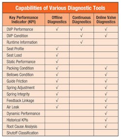
The table in Figure 2 offers a snapshot of the various aspects of valve performance and condition that can be tracked using each of the diagnostic “flavors.”
Diagnostic Capabilities & Limitations
Each of the three diagnostic information “flavors” offers a different array of information and different insight into the corrective action that should be taken to maintain the integrity of a control valve’s overall performance (Figure 3). For example, the accumulated cycles and travel displacement data obtained via continuous diagnostics can be used to determine when packing must be maintained or replaced. Offline diagnostic information allows the user to validate the valve’s response throughout its full range of motion, as well as measure such performance characteristics as valve friction, the spring setting, and the quality of the plug and seat contact (also known as seating profile).
Online diagnostics tools combine the capabilities of their continuous and offline counterparts while offering additional advantages. There is no setup involved and the DVP’s software automatically captures the data, saving time, and streamlining processes. Remote access means plant personnel are not required to enter potentially hazardous areas. The historical data captured allows plant personnel to see performance trends over time. Finally, there is the significant advantage that the tools do not interfere with the control valve’s operation.
One key performance characteristic that cannot be tracked with a DVP or with a portable diagnostic tool is seat leakage. To explain why, let us begin by reviewing how tight shutoff is achieved. When the plug makes contact with the seat, the force generated by the actuator is delivered through the stem, compressing the plug against the seat. This metal-to-metal connection is what prevents the fluid from going through the orifice (seat) of the valve. The surface finish of the two components making contact is critical to shutoff. The smallest nick or scratch can degrade the shutoff to the point that the valve does not fulfill its ANSI (American National Standards Institute) shutoff classification.
While DVPs can confirm that there is a firm and adequate contact between the plug and seat, they cannot determine the integrity of the surface finish. The only method to confirm that the valve can achieve its shutoff classification is to run a seat leak test, or close the valve and measure the flow going through it.
Usability of Diagnostic Tools
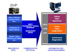
The usability of diagnostic technology has improved significantly with the emergence of such integration standards as EDDL (Electronic Device Description Language) and DTM (Device Type Manager). Prior to the introduction of such standards, the integration of field device diagnostics was complex and required significant engineering because each vendor had proprietary, standalone solutions. With EDDL and DTM, the diagnostics provided by DVPs are easily integrated with control systems and asset management software that support such standards. The user can, therefore, access the digital positioner’s diagnostics with commercially available software and without the need for software engineering.
In cases in which the host system does not support EDDL or DTM, the end-user can still integrate the information via the OPC (OLE for Process Control) standard. OPC is a communication protocol allowing the exchange of data between computers and between software. It creates a “pipeline” to move data between a computer (the server) that is connected digitally to the DVP and the computer (the client) that uses the raw data to generate and present the diagnostics.
The integration of diagnostics is straightforward with control systems that embed the HART Protocol, Foundation fieldbus, or PROFIBUS. These systems have an architecture in which diagnostic information is passed from a DVP to a user interface.
In the case of older systems that still use an analog signal, such as 4-20mA, the DVP’s diagnostic data cannot be communicated through the host system’s architecture because the system’s analog output channels are not capable of reading the HART data. The emergence of wireless standards, such as WirelessHART and ISA100, bridge that gap by allowing the data to be wirelessly communicated from the DVP to a centralized data acquisition computer.
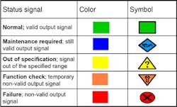
When it comes to presenting the information to the user, there are two primary industry standards for doing so in a common fashion, regardless of the DVP’s manufacturer – ISA SP75.26 and NAMUR NE 107. ISA SP75.26 applies to offline diagnostics, defining the terminology for valve diagnostics and the graphical representations of valve signatures. NAMUR NE 107 applies to continuous and online diagnostics. It categorizes various possible asset conditions and their severities and uses a set of color-coded symbols to communicate these statuses (Figure 4). The same symbols are used for devices made by various manufacturers, making them easily recognized and interpreted – much like the “Check Engine” light on a car’s dashboard.
The Next Decade – Developments to Watch
Control valve diagnostics have evolved rapidly over the past 30 years – from manual readings with gauges and calipers to artificial intelligence that can analyze a valve’s performance while the valve is in operation. Advances will come as fast, if not more quickly, over the next decade thanks to continued advances in artificial intelligence and the introduction of ultra-low-power microprocessors and sensors. These technologies and tools will have the potential for allowing additional measurements to be taken at the control valve, thus enabling more precise prediction of pending performance problems and the detection of additional valve malfunctions, such as seat leakage.
Furthermore, wireless and cloud computing could allow information to move seamlessly to specialized outside experts, allowing users to tap into their knowledge and, therefore, fueling the creation of an encyclopedia of valve symptoms, root causes and cures.
If control valves have not yet affected a plant’s performance and budget, it is likely only a matter of time before they do so. Today’s diagnostics technologies can help operations personnel prepare, help them optimize their processes, and potentially help them trim maintenance costs.
Sandro Esposito is global marketing manager at GE Energy for digital and SMART products in the company’s Masoneilan line. A 17-year veteran of the control valve and process automation industries, Mr. Esposito has extensive experience with control valve diagnostics and system integration and has been granted several patents related to digital valve positioners. He graduated from Ahuntsic College in Montreal with a degree in instrumentation and process controls. Mr. Esposito can be reached at [email protected] or 281 671-1683.
