Increasing pressure from the environmental movement and a growing awareness of our need to reduce energy consumption is driving the demand for smarter, more accurate, real-time fuel gas measurement and emissions monitoring systems. Thermal mass flowmeters (TMFMs) are an important element of the emissions control process; specifically in the measurement of mass emissions.
On November 8, 2010, the EPA passed the final rule on 40 CFR Part 98 Subpart W Mandatory Greenhouse Gas Reporting for Petroleum and Natural Gas Systems, and it became effective as of December 30, 2010. This rule requires owners and operators of facilities emitting more than 25,000 metric tons of CO2 equivalent (CO2e) to monitor and report Greenhouse Gas (GHG) emissions.
Thousands of facilities operating in the petroleum and natural gas industry are affected by these rules. The EPA is requiring the use of direct measurement of emissions from several source categories. The direct measurement requirements for fugitives have been defined and it has been determined that TMFMs exceed the performance requirements mandated by the rule.
In June of this year, the EPA also finalized the 40 CFR Part 60 ruling, requiring flow monitoring of flares in petroleum refineries. Flowrates must be continuously monitored, and the flow monitor must be able to continuously correct for temperature and pressure. TMFMs are ideal for such applications since they provide a direct flow measurement without temperature or pressure compensation and can accurately measure the varying flowrates typically found in flare applications.
Combustion Process Measurement & Monitoring
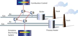
Plant managers seeking to improve burner performance must balance fuel and energy-saving measures with emissions-reduction priorities. Typically, burners are operated at air-rich conditions to allow for variations in supply pressure, heating value, etc. This excess air contributes to incomplete combustion, fuel waste, and excessive CO2 and NOx emissions. Optimizing fuel-to-air ratio helps operators obtain peak thermal efficiency over the entire range of the burner and facilitates proactive emissions control.
A wide variety of flow measurement technologies are used in these applications, but the critical factors in selecting the best flowmeter for combustion applications are direct:
-
Mass flow measurement
-
Accuracy
-
Repeatability
-
Turndown
-
Ease of installation
-
Safety and reliability
As shown in Table 1, most conventional flowmeters measure volumetric flow and require additional measurements of pressure and temperature to calculate density and mass flow. Because the TMFM measures mass flow directly and is virtually immune to changes in temperature and pressure, it provides the most reliable, repeatable, and accurate measurement. The TMFM also provides better rangeability and a lower pressure drop than conventional flowmeters.
Because it has no moving parts and can be installed via a single insertion point on a pipe or duct, the TMFM is easy to install and maintain. The instrument’s broad measurement range also makes it a good fit for monitoring very low velocity flowrates, such as found in vent gas, flare stack, and fugitive emissions applications.
Most thermal flowmeters also incorporate a totalizer and a variety of digital communication options for interfacing with emissions management systems. These systems can be used to monitor GHG emissions from industrial, institutional and commercial boilers, and they provide a simple, reliable and cost-effective method for tracking and reporting fuel consumption.
TMFMs provide a reliable, cost-effective solution to GHG emissions monitoring challenges. They directly measure mass flowrate, have no moving parts, and can be installed via a single insertion point on a pipe or duct. Other benefits include:
-
Totalizer meets air quality management requirements;
-
A variety of output signals to interface with emissions management systems;
-
No pressure or temperature compensation; and
-
Broad measurement range (100-to-1 typical); including very low velocity flowrates.
Landfill Gas: Landfill Gas (LFG) contains methane, a potent greenhouse gas. The EPA requires landfill operators to collect the methane produced on site, and where it is not being used for energy production, it must be flared to prevent its release. Landfill-Gas-to-Energy (LFGTE) facilities typically extract gases from multiple wellheads, which are connected to a common header pipe, and then recovered for a variety of uses, including:
-
Fueling on-site engines or turbines
-
Generating electricity for surrounding homes and businesses;
-
Conversion to liquid natural gas for clean vehicle fuel.
Accurate flow monitoring is essential for gathering systemwide information on the amount of gas being extracted, flared or recovered. Some of the measurement challenges in the LFG environment are changing gas compositions, varying flowrates caused by seasonal temperature changes, and wet, dirty and potentially explosive gases. TMFMs can help LFGTE operators comply with clean air regulations, as well as improve the performance of co-gen engines or methane oxidizers.
Figure 4 illustrates how flare stacks are used to burn waste gases from the plant, converting chemical and organic hydrocarbons into primarily water vapor and CO2. Some processes also use relief valves to vent flammable gases to the flare stack during upset conditions. Applications include oil and gas well drilling operations, oil refineries, chemical process plants, gas distribution infrastructure and landfills.
Flares are subject to stringent regulations, requiring operators to measure, record and report the amount of flared gases. Due to the potential for large changes in flowrates, density, pressure and gas composition, flare gas measurement is one of the most difficult and demanding flow applications. TMFMs have demonstrated their ability to measure the low flowrates typical of normal flare conditions, as well as the high velocities found in upset conditions.
Wastewater Treatment Plants: Wastewater Treatment Plants (WWTPs) use large heated digester tanks to remove and dispose of solid waste material. Inside of the digesters, bacteria break down the material that produces digester gas in the process.
Methane is a primary component of anaerobic digester gas (ADG) and a large wastewater treatment plant can produce roughly one million cubic feet of this gas each day. Most WWTPs utilize recovered gas to fuel boilers and flare off the excess. Other biogas uses include fuel for combustion engines to generate electricity, fuel for natural gas vehicles, and sale and distribution to neighboring industries and communities.
ADG is a wet, dirty gas, often containing entrained hydrogen sulfides, which may condense and accumulate on pipe walls or equipment inside of the pipe. Selecting a flowmeter with no moving parts can dramatically reduce costs associated with maintenance and repair.
Most digester gas applications operate at relatively low pressure. TMFMs create virtually no pressure drop and can be used to accurately measure these flowrates. They are widely used in WWTPs to optimize digester processes and comply with environmental regulations.
Specifying a TMFM
The most important consideration in flowmeter selection is choosing the appropriate technology. For example, some flowmeters are suitable for air and gas applications, but not useful for liquids, while others may offer the most effective solution for steam monitoring. A thorough examination of the application parameters, including plant layout, processes and installation environment can help save time, money and headaches down the road.
It is also critical to evaluate the piping requirements and flow characteristics of the fluid to be measured, including the expected minimum and maximum pressure and temperature values, as well as normal operating values. In terms of the piping setup, one should account for the following: direction, size, material, pipe schedule, flange-pressure ratings, upstream or downstream turns, valving, and available straightpipe run lengths.
Accuracy and rangeability are the most critical characteristics of a flowmeter. Most manufacturers provide these specifications for water, air or a specific gas. It is important to ensure that these specifications meet the requirements of a particular fluid or process.
Some flowmeter installation procedures are more complicated than others, and it is important to determine if the meter can be inserted directly into the process pipe or if the line must be cut, spliced or penetrated in various locations. The installation process can affect the complexity and cost of the flowmeter, as well as the instrument’s ability to maintain specified accuracy.
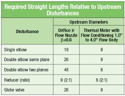
Most flowmeters require a specific length of upstream and downstream straight-run pipe to generate a well-developed flow profile, and that length will differ from one technology to another. This is especially important in retrofit installations, where additional piping may increase the cost of installation.
In-line flowmeters of all types substantially sacrifice their inherent accuracy if they are installed too close to upstream disturbances. Most flowmeters require at least 20 diameters of straight pipe downstream of the disturbance to preserve their inherent accuracy. In such cases, a non-flowconditioned meter is preferred. However, in most cases long straight pipe runs are either impractical or not available.
Most TMFMs are available with built-in flow conditioning. This technology helps eliminate velocity profile distortions, swirl and temperature stratification in the gas stream, and greatly reduces upstream piping requirements. Table 2 compares straight length requirements of an orifice plate to a TMFM with flow conditioning, in a variety of constrained piping conditions.
Considering Thermal Flow Measurement
Improved performance, enhanced userinterfaces and reduced cost-of-ownership have made TMFMs the instrument of choice in many emissions monitoring and control applications. Because mass flowrate is the quantity of direct interest in emissions auditing applications, this instrument has significant advantages over volumetric flow measurement devices.
Because the thermal meter does not require ancillary equipment to calculate gas density, it reduces initial cost, installation costs, and maintenance costs. New field-calibration technologies further enhance the value of the TMFM in environmental monitoring applications.
Flow Calibration Requirements for TMFMS
Under the new U.S. EPA rules, flow measurement device calibration accuracy must be validated on a periodic basis. In the case of 40 CFR Part 98, there are ASME standards for certain meter types, but the rule states that the flowmeter manufacturer’s recommendations may be used for any meter not specified by an ASME standard. In general, that requires that the meter be re-calibrated every year. Since an ASME standard is not listed in this Title for TMFMs, the manufacturer’s recommendation can be used (commonly a two-year period).
However, it is becoming more common for TMFM manufacturers to offer ways to validate the calibration of a meter in the field. Typical procedures for calibration validation of TMFMs may include stopping the flow and removing the meter from the pipe, looking up data on the flowmeter’s factory calibration certificate, measuring electrical characteristics to evaluate performance, setting process pressure to manufacturer’s calibration pressure and connecting auxiliary test equipment and/or test gases to the flowmeter.
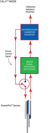
This complex and time-consuming routine can be costly and subject to operator error. But there is technology available to help in this process. For example, Fox Thermal Instruments recently developed an insitu calibration routine, called the CAL-V, that validates the flowmeter’s calibration accuracy by testing the functionality of the sensor and its associated signal processing circuitry, allowing the operator to validate instrument calibration in the pipe at actual process conditions with a push of a button.
Matching data within established tolerances confirms the meter is measuring accurately. CAL-V is an operator-initiated test that can be performed at any flowrate, including zero, and is completed in up to four minutes.
Tim Modders is Regional Manager for Fox Thermal Instruments. He holds a BS in Electronic Engineering and has more than 30 years experience with instrumentation and industrial process controls. Thermal Mass Flow technology and its applications and development have been the focus of his work for the past 20 years. Contact Mr. Modders at (831) 384-4300 or [email protected].
