For process plants, terminals and tank farms designed to receive and send out millions of gallons of flammable hydrocarbons, the ability to safely handle such movements should be a fact of life. The same is true for smaller companies that maintain tens-of-thousands of gallons of products or feedstocks. Even if their products are benign, a large enough spill of practically anything can create an environmental incident.
This is precisely why tanks that are routinely filled and emptied during normal operation need to have a mechanism to avoid overfilling incidents. The concept is basic: It is impossible to put 50,000 gallons of liquid into a 40,000-gallon tank. Yet such attempts happen, usually because operators do not realize the condition of the contents of the existing tank. Insurance data shows that for all the tanks around the world, there is one overfilling incident for every 3,300 filling operation. Perhaps that sounds like a small proportion, but overfill accidents can be devastating. Consider the following two well-documented examples.
In Hemel Hempstead, England, December 2005, the Buncefield oil storage depot was the site of the largest explosion in that country since World War II. Operators filling a tank with gasoline were unaware of its full condition, and 250,000 liters flowed out of vents onto the ground. Truck drivers approaching the facility called the control room and warned of the situation, but it was too late; the fuel found an ignition source. There was no functioning level instrument on the tank nor was there a functioning overfill protection system.
In Bayamón, Puerto Rico, October 2009, the Caribbean Petroleum (CAPECO) terminal was transferring more than 10 million gallons of unleaded gasoline from a tanker ship to storage tanks. Operators were trying to spread the large load among multiple tanks, but one of the tanks had a malfunctioning mechanical level gauge. Once filled, gasoline flowed out of the vents, leaked through the dikes and ignited when it reached electrical equipment. Within seconds, the explosion caused a blaze that destroyed 17 of the facility’s 48 tanks.
There are other examples, but the point should be clear: An overfill can have devastating consequences, and an overfill prevention system depends on the right combination of level measurement instruments, operator interfaces, safety controls systems and final control elements. Additionally, condition monitoring of those components helps ensure an operational safety system. This article looks at how these elements can and should interact.
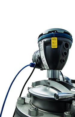
Figure 2. Rosemount Radar Level Transmitter available in an SIL 3-certified version
Operator awareness
Operators must have an accurate, complete and real-time picture of the contents of every tank. One common recipe for an overfill incident is when operators begin pumping liquid into a tank without realizing it is closer to being full than they thought. It should be easy to see the contents of any tank from the control room, but this depends on having accurate and reliable level instruments for every situation. In both the Buncefield and CAPECO incidents, level instruments were malfunctioning.
Safe and reliable proof-testing
Proof-testing is necessary to make sure the safety system will work when it is required. Unlike a basic process control system, an overfill prevention system does not operate on a regular basis. It only needs to operate when tank level reaches an extreme point. But to assure it is operational when needed, proof-testing is required on a regular basis, and partial proof-testing can extend the time period before a full proof test is required.
Traditional proof-testing methods involve multiple technicians in the field working with someone stationed in the control room to verify the system’s response. The field technicians must climb tanks to access instruments and attempt to cause them to trip, exposing them to hazardous contents and increased safety risks. Performing proof tests this way is error-prone and time-consuming. It can also interfere with production, causing negative financial impact.
Partial proof-testing of level instruments can now be accomplished easily from the control room with devices that have been designed especially for use in safety-instrumented systems (SISs). Devices that provide a high safe failure fraction can also help achieve a higher level of safety.
Additional condition monitoring aids, such as a digital valve controller for SIS applications, have the potential to do partial stroke testing of the valves as well as monitoring the health of valve assemblies.
Figure 3. Rosemount Vibrating Fork Level Detector available in an SIL 2-certified version
Automatic shutoff
The system controlling filling operations must also have effective alarms combined with automated shutoff. When using a manual filling procedure, operators must be made aware when a high-level threshold has been crossed while there is still plenty of time to take corrective action before an automated shutoff system intervenes, which will likely cause some disruptions. Naturally, this approach depends on having effective instrumentation.
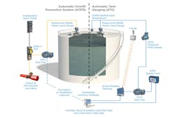
A risk assessment should be performed for every tank to determine the level of safety required. Automated filling control systems must be equipped with a safety system capable of stopping the filling operation before the tank begins to overflow (see Figure 1). Such an SIS involves three functional components: a level instrument, a logic solver and final control elements. The actual design of an SIS is complex, and there are experts to consult for help, but to understand the basic concepts, the following describes each element individually and explores valuable advances.
The level instrument (like the one shown in Figure 2) can use a variety of technologies to provide a continuous or point level measurement. It must be able to function independently of any other instrument on the tank, and it must have this safety function as its primary duty. Vibrating forks (as shown in Figure 3) are commonly used in this application because they are simple and highly reliable. Recent advances in diagnostics allow for condition monitoring of level instruments while they are online, which allows easier partial proof-testing.
The logic solver is a complex data reader and performer. Its job is to read the signal from the instrument and perform a specified function when the sensed value crosses the threshold. Like the instrument, it must be a certified safety device, and it must be able to perform its function independently without depending on any other part of a larger automation system. It may send data to the larger process automation system, but its real-time control function must be entirely self-contained.
What action the logic solver takes is determined by the nature of the equipment. Typically, it will shut down any pumps moving liquid into the tank and will close strategic valves to contain the flow. The logic solver may respond immediately upon receiving the signal from the level instrument, or it may have a delay built in to allow for a brief transient.
Turning off a pump is easy enough, but closing valves can be more complex; this is where the final control elements come in. Again, these must be capable of functioning independently in any situation. If the system is completely automated, the relevant valves should be outfitted with actuators designed for SIS service. Some locations still depend on manual valve closing to complete an emergency shutdown action. Besides the main drawback of requiring personnel to go into the field in a potentially dangerous situation, a manual system also depends on a person’s ability to locate and close the correct valves quickly enough to forestall a release.
Following design requirements
These systems must be designed appropriately, observing all relevant safety standards and best practices, such as IEC 61511, API 2350 and potentially others. Newer technologies are also replacing many legacy mechanical level instruments.
When choosing level instruments to replace these devices, selecting a third-party SIL-certified device will provide many additional benefits besides measurement reliability. They can make safety loop calculations much simpler and more reliable.
While it is helpful and even perhaps required to use safety-certified instruments and supporting devices, these alone do not ensure an effective SIS. They must be applied and integrated correctly. Once installed, the systems must be tested and verified, and all appropriate procedures should be followed on a regular basis. Choosing devices that provide easier proof-testing will ultimately reduce the life cycle costs of an overfill prevention system.
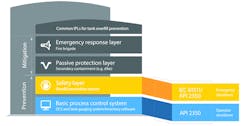
Figure 4. Prevention and mitigation layers of protection are designed to prevent catastrophic incidents.
Layers of protection in storage tank safety systems
All of these systems are designed to serve as layers of protection for the plant (see Figure 4), people and surroundings, while avoiding product loss, by providing the following functionality:
When operators can see an accurate picture of what is in each tank and monitor filling operations, they can control the outcome correctly and avoid problems.
Should operators lose track of what is happening, an overfill prevention system can help ensure the operation can be brought under control before an incident escalates.
Even if operators do not respond or there is a failure of the process automation system, an automated overfill prevention SIS can perform an emergency shutdown without the need for any human intervention.
These three types of actions all avoid a release of liquid. In the event of everything failing, mitigation layers take over in the form of dikes and emergency response services. Naturally, these are drastic situations and well beyond what anyone wants to see happen.
Putting it all together
When dealing with tanks operating in process industries or those that store products at a tank farm or terminal, one of the major hazards to avoid is overfilling the tanks. This is especially important with chemicals that may explode, catch on fire or affect the health of people or the environment.
Effective tank management involves safety but should encompass far more. It begins with accurate and reliable level measurement instruments using the best technology for the application. Data must be collected, processed and displayed appropriately to provide a high degree of operator awareness. In both the Buncefield and CAPECO incidents, the mechanical level instruments had failed and the operators did not know it.
An effective system integrated with sophisticated instruments avoids many of the failure modes common to older technologies and can even perform self-diagnostic routines to verify every element is functioning correctly. In the event of an instrument failure, an alarm is activated to make operators aware of the issue.
Third-party certified devices make safety loop calculations simpler, because part of the work has already been done by the supplier. Devices designed especially for SIS applications will offer even more advantages due to specific features, such as online partial proof-testing, designed to reduce safety life cycle costs. It is important to take the time to select devices designed specifically for use in an overfill prevention system.
AnnCharlott Enberg is a functional safety manager with Rosemount Level, Emerson Automation Solutions.
Lydia Miller is a senior marketing engineer with Rosemount Level, Emerson Automation Solutions.


