Steam is commonly used in the upstream and downstream hydrocarbon industries for steam injection and process heating. Accurate flow measurements are needed to maintain process efficiency, detect leaks, and account for consumption. Cost-effectively ensuring high accuracy, repeatability and reliability is a challenge, especially in cold climates. In the following article traditional practices are reviewed and new best practices are established. These new practices have demonstrated improvements in reliability and turndown, at lower initial and life cycle cost.
Traditional Practices
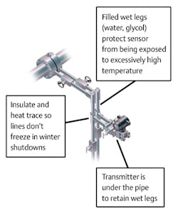
The traditional steam differential-pressure (DP) flowmeter is illustrated in Figure 1. In this installation, the transmitter is installed under the pipe. Columns of condensate form in each of the impulse lines leading to the transmitter. These “wet legs” of condensate are hot where they contact the steam, but cooler by the time they reach the transmitter.
This prevents the oil in the transmitter from overheating past its vapor pressure, which would cause the oil to flash and rupture the thin metal diaphragm in the pressure transmitter. Users manually fill the wet legs with condensate prior to startup and should refill the wet legs after any shutdown. If the wet legs are not properly refilled, one side might initially contain a higher column of water than the other. Although the lines will eventually equalize on their own, even a small difference causes a significant error, particularly at the lower flowrates typical of startup conditions.1
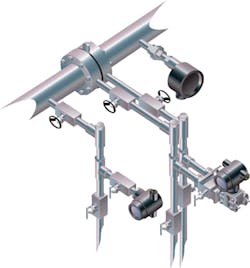
Although Figure 1 shows only a single DP transmitter and primary element, since steam is compressible most real installations utilize density compensation via a second line pressure measurement, temperature measurement, and a flow computer, as shown in Figure 2.
In outdoor installations in cold climates, the fluid in the impulse lines is farthest from the process – nearest the transmitter – particularly during planned or unplanned process shutdowns. This can cause measurement errors, leaks and failures, as the ice expands and ruptures the transmitter diaphragm. To prevent this, steam or electrical heat tracing is used to maintain the impulse lines above freezing. These systems typically consist of electrical heating cable, a thermostat or controller, and a power distribution panel. Heat tracing is costly to install – typically $3,000-$4,000 per system. Ongoing energy costs are up to $500 per year in northern climates. Worst of all, heat tracing systems require frequent maintenance. Failure of the heat-tracing system – either on or off – can result in freezing or overheating of the sensing lines, possibly leading to transmitter failure.
The requirement for a wet leg also limits flow performance and turndown. In a typical installation, normal variation in the steam flowrate will cause variable flashing at the interface between the steam and the wet leg, similar to the shrink/swell observed in a boiler drum. In a typical installation, this variable flashing causes noise of +/-0.2 inH2O (0.5 mbar), causing flow variations of up to 2 percent of full scale. Even though newer, smart transmitters – especially those that have been flow characterized by the manufacturer – are capable of 15-to-1 or better flow turndown, wet leg instability limits real-world turndown in most steam applications to 4-to-1 or worse. To minimize the impact of this wet leg instability, users will often size their primary elements to produce a higher pressure drop. This requires a lower beta ratio, causing higher permanent pressure loss in the application.
Rethinking the Technology Solution
For nearly two decades, smart pressure transmitters from most manufacturers have been supplied with integral temperature sensors. As a distinction from the sensor used to measure fluid temperature – for density compensation – these sensors measure the temperature of the pressure sensor itself. As the sensor heats and cools due to changing process and ambient temperatures, its oil and mechanical components expand and contract. The transmitter microprocessor uses this sensor temperature input to compensate for these effects and minimize their impact on measurement accuracy.
Users with HART, FOUNDATION fieldbus or WirelessHART transmitters connected to an asset management system can conveniently log and trend secondary variables, such as sensor temperature.2 Suppliers can therefore monitor sensor temperatures for flowmeters installed in the field, as well as for transmitters returned to the factory for post-mortem failure analysis. Analysis of data from hundreds of installations has revealed that sensor temperature is consistently lower than expected for any given installation. This is not useful in predicting sensor temperature in a “traditional” installation, in which the user installs whatever length and diameter of sensing lines best fit the installation. However, sensor temperature can be reliably predicted from process temperature for an “integrated” DP flowmeter. These devices include the primary element, the transmitter(s), and any isolation valving. They arrive pre-assembled from the supplier, which minimizes cost and risk of field assembly.
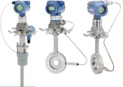
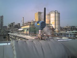
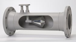
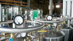
Figure 3 shows DP flowmeters with the transmitter connected to either wafer-style orifice plate, or averaging Pitot tube, with integral manifold, temperature measurement, and multivariable transmitter. For each installation, the user can obtain continuous, simultaneous measurement of both the process temperature and the sensor temperature. The annubar-type of differential-pressure flowmeter is typically used in larger lines and when the user aims to reduce permanent pressure losses. The compact wafer-style primary element is better suited to smaller lines, and the “conditioning” version, with four holes, minimizes the need for straight upstream or downstream pipe. Figure 4 shows an installation of a conditioning compact orifice flowmeter, mounted on top of the steam pipe, which has been in operation since June 2008 in Albany, NY.
Laboratory tests and real-world installations have revealed that enough heat is dissipated by the short neck of the integrated manifold and the manifold block itself that the transmitter can be directly installed without risk in a process temperature of up to 230 C (450 F) without neck insulation. Using normal insulation for personnel protection, the limit for either type of primary element was found to be 205 C. This temperature corresponds to 235 PSIG saturated steam.
New Best Practice – Transmitter on Top
Installing the transmitter above the pipe eliminates wet legs. This results in a simpler, lower-cost installation. No wet legs means no instability, significantly improving potential turndown. No risk of wet leg freezing during shutdown means no need for heat tracing, and its associated capital and operating costs.
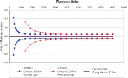
Figure 5 demonstrates the improvement in turndown possible by changing the orientation of the flowmeter from the traditional “transmitter underneath” to the recommended new best practice. With identical transmitters, turndown is dramatically improved in this low-pressure heating steam application. High turndown is useful in heating applications that exhibit wide seasonal swings in steam demand.
Recommendations
Within the limits described here and per supplier recommendations, users can install steam flowmeters with the transmitters above the pipe without wet legs. This new best practice is less expensive to install and operate, provides higher reliability with less maintenance, and provides high accuracy and turndown.
Mark Menezes manages Emerson’s measurement and flow business for Emerson Process Management (Rosemount) in Canada. Mark earned a degree in Chemical Engineering from the University of Toronto and also holds an MBA. He has 21 years experience in industrial automation. Mark can be reached at 416 459-5935 or [email protected].
References
1. Menezes, Mark, “Energy Management Best Practices and Software Tools,” Energy Engineering, April 2005.
2. Menezes, Mark, “Improve Plant Safety with Advanced Measurement Diagnostics,” Chemical Engineering, October 2000.
3. “Top Mount Installation for DP Flowmeters in Steam Service,” Rosemount white paper, 00870-0200-4809.
This article is based on a paper that was originally presented at the Canadian School of Hydrocarbon Measurement, April 2010.
