Plants often use multistream sampling systems to monitor as many process streams as possible with a single process analyzer. Such systems allow a plant to select a single process stream for analysis and block all others.
To achieve the best results, system designers should ensure their multistream switching systems follow three primary design requirements, including:
- Properly isolating samples to prevent cross-stream contamination
- Ensuring fast responses so final measurements are representative of real-time process conditions
- Minimizing flow upset to mitigate pressure spikes and potential sample phase changes
This article reviews design strategies for meeting these objectives to help plants effectively use multistream switching systems to optimize their analyzer networks.
Proper sample isolation
It is necessary to isolate each sample to prevent a stream not selected for analysis from contaminating the stream that is being analyzed. Using reverse flow or reverse pressure ensures that a leak across a valve seat will flow away from the stream under analysis and therefore not contaminate it. Avoiding dead legs — areas of reduced flow that trap older sample material — is also critical to prevent older samples from contaminating a new sample.
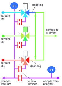
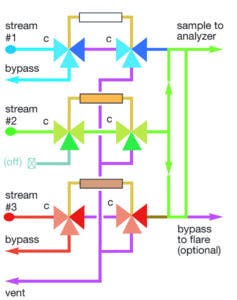
The reverse flow technique prevents dead legs by ensuring every tee in the line to the analyzer is flowing in all its legs. For example, the block-and-bleed system in Figure 1 allows the selected sample to flow into the entire flow path and out from two outlets — one flowing to the analyzer and one to a bypass line or vent.
Figure 1. The reverse flow technique used to prevent dead legs in this block-and-bleed assembly featuring three-way valves allows the selected sample to flow into the entire flow path. All figures courtesy of Swagelok, "Industrial Sampling Systems," ©20131
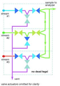
The reverse pressure technique prevents dead legs by ensuring every closed valve seat has a lower pressure — typically atmospheric — on the other side of the seat. Therefore, any seat leakage flows to a vent and cannot contaminate the sample. Every tee in the flow path for the double-block-and-bleed (DBB) system (discussed later in more detail) becomes a three-way valve, leaving no dead legs.
Quick responses
Time delay represents the total time from the sample being drawn to producing an analyzer result. Shorter delays enable operators to make any necessary process adjustments sooner. Minimizing the presence of dead legs, mixing volumes and potential adsorption surfaces, such as filters, in the common flow path to the analyzer promotes quick responses after stream switching, as does ensuring all lines are flowing, even when not being analyzed.
Minimum flow upset
When selecting different streams for analysis, avoid drastic flow changes, as they may create pressure spikes that could damage sampling system components. In addition, a sudden flow and pressure increase may cause a gas sample to condense.
It can be challenging to minimize flow rate changes because stream selector systems differ in how they treat lines not selected for analysis. For instance, systems that completely stop the flow of unselected inlet lines leave old samples in upstream lines that will need to be purged before the next analysis. On the other hand, systems that ensure a continuous flow, even when the stream selector valve is closed, do not maintain constant flow, as flow in the transport line will increase when selecting a stream.
Systems that maintain the same flow at all times offer the best potential. To achieve constant flow, the stream selector valves must simultaneously shut off a stream’s line bypass flow when selecting that stream for analysis via the common flow path to the analyzer.
Configuring stream selector valves
Some key design configurations can help enhance system reliability and achieve some or all of the three primary design objectives.
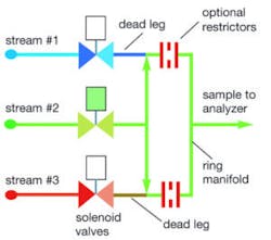
Ring manifold: A simple manifold design has dead legs at each tee junction. However, a ring manifold design (see Figure 2) reduces the volume of dead legs, especially if tee fittings can screw directly into the valve bodies. With an integral flow loop and ports for various process and analytical stream connections, a ring manifold generates about the same flow resistance for each stream to help maintain a constant flow to the analyzer when switching streams. Unfortunately, the design in Figure 2 does not protect against possible valve leakage, making it unsuitable for switching process streams alone.
Figure 2. An integral flow loop inside a ring manifold helps maintain a constant flow to the analyzer when switching streams.
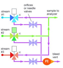
Line bypass: Adding a continuous bypass loop to the sample line at a location close to the stream switching system is the simplest way to maintain flow (see Figure 3). The bypass line may include a needle valve and flowmeter or a critical orifice to maintain flow. This design offers a fast response when switching streams. However, sample contamination from valve leakage may still occur. In addition, because the line selected for analysis flows more rapidly than the unselected lines, the sample flow is not constant.
Figure 3. A continuous bypass loop added to the sample line close to the stream switching system helps the sampling system better maintain a consistent flow for more timely and accurate analyses.
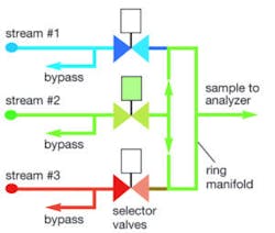
Valved bypass: The three-way valves shown in Figure 4 maintain flow in the lines not selected for analysis and achieve two of the three design objectives. By setting the analyzer flow to equal the bypass flow, flow changes can be eliminated during switching. Responses will also be fast in this design. However, sample contamination is still possible from valve seat leakage and small dead legs.
Figure 4. A valved bypass configuration can help a sampling system maintain consistent flow and produce fast analyzer responses.
Double-block-and-bleed system: System designers can address — but not necessarily fully meet — the three design objectives by using various configurations of a DBB system. Such systems are highly effective at eliminating dead legs and isolating samples to avoid contamination. A DBB arrangement (see Figure 5) has dual block valves driven by a common actuator. First, a primary valve blocks the incoming sample stream and bleeds the connecting tube to a vent. Next, a secondary valve blocks the connecting tube and opens a cascaded path that allows the selected sample to flow to the analyzer. Dead legs are thereby eliminated. The common vent header, which is at a lower pressure than the stream flowing to the analyzer, disposes of any valve leakage, making cross-stream contamination virtually impossible.
Figure 5. Every tee in the flow path in this reverse pressure DBB system becomes a three-way valve, eliminating dead legs.
Regarding response times, designers need to watch for time delay with some DBB assemblies. The DBB’s cascading valve path causes each sample to encounter a small but finite flow resistance. Therefore, streams passing through more valves have lower sample flow and higher time delay.
Adding a line bypass to maintain inlet line flow (see Figure 6) will help designers achieve a faster response from the analyzer when switching samples. However, it will not keep the sample line flow constant, as additional flow occurs when selecting a stream for analysis.
Figure 6. The line bypass in this double-block system maintains flow in the inlet lines to help achieve faster analyzer responses.
Double-block system with a ring manifold: Adding a ring manifold to a vented double-block valve system provides additional two-way and three-way valve arrangements that can help address the three design objectives.
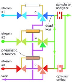
The basic valve circuit in Figure 7 uses a ring manifold with a two-way primary block and a three-way secondary block-and-vent. The dual valves block each unselected stream in two places and vent the line between them to prevent cross-contamination. However, the ring manifold may introduce small dead legs at each connection.
Figure 7. A two-way primary block and a three-way secondary block-and-vent in this double-block assembly isolates the sample. A ring manifold maintains consistent flow.
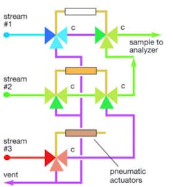
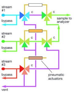
The design in Figure 8 uses three-way valves in the primary block position to maintain continuous flow in the inlet lines whether a stream is selected or not. However, it is necessary to include an initial bypass or fast loop upstream of the stream selector if the streams all have different flow rates. The sample from each sample takeoff point flows to the stream selector and passes through the primary block valve and out via the bypass line. By setting each bypass flow to equal the flow rate taken by the analyzer, each stream will have the same flow rate whether its selection valve is open or closed.
Figure 8. Whether a stream is selected or not, this double-block assembly uses three-way valves with a bypass in the primary block position to hold each stream at a constant flow rate.
Finally, fast response times are likely with a double-block valve system featuring a ring manifold because flow resistance is essentially the same for each stream.
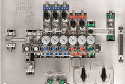
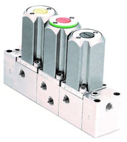
Modular stream selection valves: Another viable option for meeting the design objectives is a compact stream selector valve assembly (see Figure 9), which combines DBB functions into one compact valve body. It has an integral actuator that operates three two-way valves in unison. Bolting multiple stream selector valves together can manage numerous streams. The compact assemblies enable faster analyzer response times even at lower flows due to their minimal flow paths and low internal volumes.
Figure 9. Stream selector valves combine DBB functions into one compact valve body and can be bolted together to create a multistream switching system.
Connecting several stream selector valves together automatically deploys a ring manifold that extends the length of the valve assembly. This pathway helps to maintain a constant flow to the analyzer when switching streams.
With a stream selector valve, a DBB function isolates samples by ensuring any leaking fluid from other streams escapes via a vent and cannot contaminate the stream being analyzed. The valve’s internal design also preserves the analytical purity of the sample by eliminating unswept tees and cavities along the internal flow path. The three-stream design in Figure 10 is a good example, as it mitigates a potential deadleg at the vent valve by purging the vent valve seat with a continuous flow of sample fluid. The design also minimizes dead legs in the ring manifold by purging all the closed outlets with the selected sample flow.
Figure 10. An integral ring manifold inside this assembly of three stream selector valves helps to maintain a constant flow to the analyzer when switching streams.
Meeting the primary design objectives to optimize process analyzers
Multistream sampling systems are an effective way for plants to reduce their total number of process analyzers. However, designers should only use multistream switching when measuring the same analytes at about the same concentration in each stream. When multistream switching is a viable option, following the primary design objectives of sample isolation, quick analyzer responses and minimum flow upset will help to enhance analyzer reliability.
References
- "Industrial Sampling Systems: Reliable Design and Maintenance for Process Analyzers" (2013), authored by Tony Waters and published by Swagelok Company. www.industrial-sampling-systems.com.
Randy Rieken is market manager for chemical and refining for Swagelok Company. He is responsible for the development and implementation of chemical and refining market-driven strategies. Rieken joined Swagelok in November 2014 and has more than 25 years of global business development experience. He can be reached at [email protected].
