Coiled tubing cleanout plays a critical role in achieving and maintaining maximum production and optimal operation of a well. It is an intervention technique that involves one continuous piece of flexible tubing fed down the wellbore to flush out debris, sand or other blockage and restore productivity in a controlled manner. Cleanout may be planned as part of well completion or other operation, or it may be performed as needed to address accumulated sand.
Coiled tubing cleanout is costly, resource-intensive and risks further complications, such as coiled tubing getting stuck in the well. If this happense tubing becomes lodged in the well, it can be a substantial project to clear the tubing, and in a worst-case scenario it can mean blocking in and writing off the well. Short of the stuck tubing risk, an ineffective cleanout carries potentially severe consequences that may not reveal themselves until normal production has resumed. An ineffective cleanout can result in continued poor production, increased expense associated with repeated cleanouts and damage to surface equipment.
Ensure effective cleanouts
Significant effort has been put into modeling the process and designing fluids, tools and processes to ensure cleanout is effective, operates efficiently and avoids major complications. Fluid viscosity and velocity are among the best factors for determining whether the cleanout will be effective. This is because the fluid velocity needs to exceed the settling velocity of the particles for the debris to be lifted up the well. Particle settling velocity is determined by the balance of gravity and the drag force of the fluid flowing past the particle. Fluid with a higher viscosity will have a slower settling velocity for the same particle.
Flow rate and viscosity are such critical aspects of a cleanout, and relatively simple parameters to measure, that contracts for the service are commonly written around maintaining these process conditions within some specifications.
Fluid viscosity that is too low can cause:
- Debris or sand to settle in the well, potentially causing stuck tubing
- An ineffective cleanout that fails to remove the debris
- The need to pump the fluid at higher velocities to lift sand and debris
It is vital to monitor for viscosity that is too low since it can cause a catastrophic stuck tube. Viscosity that is too high can cause issues such as:
- Increased power consumption
- Unnecessary stress on equipment
- Inability to maintain high enough velocity in the tubing
Because coiled tube cleanout is so common, the operation must be kept as efficient as possible. The outcome of these pressures is an increase in real-time monitoring cleanout process automation, as well as a move from batch-blended fluids to inline cleanout fluid blending. Tight specifications for cleanout fluid viscosity, and especially inline blending to reach those specifications, requires active monitoring of the fluid viscosity as it is pumped into the coiled tubing.
Viscosity monitoring
Several options exist for monitoring viscosity. They range from basic, manual methods like the Marsh funnel to real-time measurement with self-diagnostics. The Marsh funnel method requires a trained technician to time how long it takes for a volume of fluid to pass through a funnel. This method assumes a technician accurately measures time and volume for a reasonably accurate result. The quality and consistency of the measurement relies on the individual taking the measurement, and it increases the exposure of operators to the cleanout fluid. The data must be manually entered into a log. Viscosity measurements will be infrequent and present opportunities for uncertainty and human error.
Inline rheometers offer viscosity measurement at process conditions, avoid chemical exposure and eliminate dependence on operator training. However, they cannot measure non-Newtonian fluids, variance with flow regime, large errors if entrained gas is present, and being shut in – measuring fluid that is not part of the process. An inline rheometer that experiences one of these issues would give no indication of an error since no additional measurements could be used to create diagnostics.
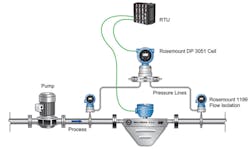
A system for real-time viscosity monitoring made up of a Coriolis meter and differential pressure measurement offers improvements. With no moving parts, the Coriolis meter reduces failure risk.
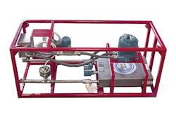
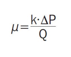
The viscosity measurement system (see Figure 1) consists of a ½-inch slipstream piping arrangement with a pump to regulate flow rate at 1 to 5 gallons per minute (gpm) through a Coriolis meter. A differential pressure measurement is taken across the Coriolis meter, with isolators on the pressure taps. The viscosity can be determined using the Hagen-Poiseuille equation:
Where:
- Q is volume flow rate, as measured by the Coriolis meter
- μ is dynamic viscosity
- ΔP is differential pressure measurement
- k is a constant, based on units and physical properties of the Coriolis meter, which are known by the manufacturer
This method requires a laminar flow regime, so it is placed in a slipstream. The calculation can be performed in a remote terminal unit (RTU), where it can be combined with other fluid information, such as density, temperature and alarms that indicate two-phase conditions and meter health. Limits for viscosity or other properties can trigger notifications.
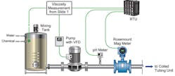
The RTU can be programmed to provide suggested slipstream flow rates to get best measurement results, or it can send a control signal to a variable frequency drive for the pump. Full-stream flow measurement, pH and other information from the coiled tubing system can be simultaneously logged in the RTU to provide a full picture of the operation (see Figure 2). With all this process information in one place, it provides a platform for setting up diagnostics and notifications for system performance.
Conclusion
With Coriolis-based viscosity measurement in the slipstream of the cleanout process, critical well protection and the information needed to optimize efficiency and reduce wasted cleanout fluid exists. It becomes easier to meet the increasing demands for tighter process controls and avoids issues with traditional viscosity measurement methods.
Justin Hollingsworth is the industry applications engineering manager at Emerson Automation Solutions. He is part of the Application Innovation team.


