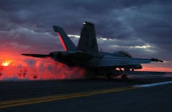
Defense contractor General Atomics (GA) is developing the next generation of aircraft catapult launch systems for United States Navy’s new Gerald R. Ford-class aircraft carriers. The Electromagnetic Aircraft Launch System, or EMALS, utilizes a breakthrough linear motor technology instead of conventional steam pistons.
A technological advance, EMALS provides a controlled acceleration of aircraft to takeoff speed. Other advantages of EMALS in comparison to conventional steam systems include lower weight, reduced operations and support costs, and expansion of the operational envelope to launch a greater range of aircraft weights and reduce fresh water requirements.
The Challenge
Accelerating a fully loaded strike aircraft to its launch endspeed using linear motor technology generates heat in both the power system and the motors, which must then be dissipated by a cooling system. The cooling water in the system needs to be actively monitored and controlled to ensure proper cooling of these systems, which requires an accurate and dependable flowmeter.
GA reviewed the available flowmeter technologies on the market in terms of their measurement accuracy, dependability, and installation space requirements. The space aboard a ship is always a limited environment and must be used efficiently. A key consideration in the selection of the flowmeter was the fact that the coolant piping system layout included elbows in and out of plane, causing swirl and cavitation that affects the accuracy of many flowmeter sensors.
A failure to accurately report the flow of cooling water is serious because it indicates the power system and/or drive motors are not being cooled and could potentially impact the system’s ability to meet operational requirements. The U.S. Navy has one of the strictest testing requirements in the world, designed to ensure key systems will remain operational in all weather, seas and combat operations.
After evaluating and testing various flowmeter technologies, GA’s engineers contacted McCrometer to discuss the problem of finding a flowmeter technology that is highly resistant to flow swirl and cavitation. The McCrometer applications team recommended the V-Cone flowmeter. Sample V-Cone flowmeters were purchased for evaluation and testing.
The Solution
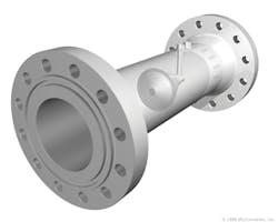
McCrometer’s rugged differential pressure (dP) V-Cone flowmeter is designed for the EMALS coolant monitoring system. With its built-in flow conditioning technology, the V-Cone flowmeter eliminated the need for long straight pipe runs to provide accurate, repeatable flow measurement in swirl and cavitation-prone piping environments.
At the same time, the V-Cone flowmeter’s compact design reduced installation real-estate requirements, allowing for more flexible instrumentation layouts and making it a good fit for the constrained shipboard environment.
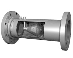
The V-Cone flowmeter utilizes a centrally located intrusion that redirects the flow to the outside of the pipe and conditions the flow by reshaping the velocity profile, all but eliminating the need for straight pipe runs. The V-Cone flowmeter requires straight pipe runs of only 0 to 3 pipe diameters upstream and 0 to 1 pipe diameters downstream.
The V-Cone flowmeter measures fluid flow by utilizing the conservation of energy theory, which basically states that in a closed system, energy can be neither gained nor lost. According to the PV=nRT equation, pressure multiplied by volume equals temperature while “n” and “R” are constants. Imposing a volume change within the pipeline, results in a differential pressure drop that can be measured directly.
McCrometer’s V-Cone flowmeter places a “V-shaped” conical intrusion centrally in the line, redirecting the fluid to the outside of the pipe and around the cone. One pressure-sensing tap located upstream from the cone measures static pressure while another pressure-sensing tap measures the low pressure created by the cone on the downstream face of the cone itself.
This pressure difference is incorporated into a derivation of the Bernoulli equation to determine fluid flow. As the fluid moves past the cone, very short vortices are formed that result in a low amplitude, high-frequency signal optimal for excellent signal stability. The V-Cone flowmeter maintains +/-0.5 percent accuracy and +/-0.1 percent repeatability over a 10-to-1 turndown, and the cone conditions the fluid such that there is relatively low permanent head loss.
The low permanent head-loss achieved by the V-Cone flowmeter results from the shape of the cone itself. The shape of the cone minimizes energy losses commonly caused by areas of low flow, cavitation and erratic flows. Each V-Cone flowmeter is sized to meet desired application requirements and may be specifically designed to have high or low head loss. Regardless, the overall energy consumed by the V-Cone flowmeter is minimized because of its inherent characteristics.
The turbulent vortices produced by the V-Cone flowmeter condition the fluid flow to be homogeneously distributed and extremely stable. It is this turbulent flow that actually protects the cone, as well as the surrounding pipe. The turbulent flow forms a boundary layer against the pipe wall and cone protecting it from particle impingement, which can cause deterioration or buildup on the surfaces.
Normal surface deterioration in flowmeters, piping and other equipment occurs as a result of fluid sheer stress. Shear stress creates a problem where there is a solid boundary layer in direct contact with the walls of the pipe. Shear stress occurs in laminar and unstable turbulent flows.
The V-Cone flowmeter’s very stable turbulent flow all but eliminates this shear stress and consequently results in no surface deterioration. Additionally, due to the shape of the cone, there is little chance of cavitation on the backside of the cone to erode the surface.
Results
McCrometer’s V-Cone flowmeter solved the fluid flow measurement challenge presented by the EMALS cooling system. The V-Cone flowmeter’s minimal space and straight pipe run requirements worked well within the tight-fit shipboard environment with a high level of accuracy.
After a short and successful preliminary test period, the V-Cone flowmeters were adopted for all EMALS cooling water metering. The first four batches of V-Cone flowmeters were supplied to General Atomics in 2011.
Nicholas Voss is a Global Product Manager at McCrometer with a decade of experience in fluid flow measurement. His experience includes development of components for liquids and wet and dry gases. Mr. Voss has a bachelor’s degree in Mechanical Engineering from the University of California, Riverside. He can be reached at 951 652-6811 or [email protected].
www.mccrometer.com
NAVAIR Public Release 2012-947. Approved for public release; distribution is unlimited.


