Reliability and efficiency go hand-in-hand in many aspects of pump selection because generally, a pump that has been selected and controlled properly for the normal operating points will operate near its best efficiency point (BEP) flow, with low forces exerted on the mechanical components and low vibration — all of which result in optimal reliability.
Pumping applications come in all shapes and sizes, and the requirements and consequences of not meeting the requirements or premature pump failure vary greatly for each application. Therefore, it is not possible to state generically how a pump should be selected or specified for design and performance, thus this article focuses on selecting a pump to operate in the preferred operating region (POR) — with net positive suction head (NPSH) margin above the net positive suction head required (NPSHR) and with acceptable vibration — to meet the goal of reliable and efficient pumping. Three American National Standards that should be referenced provide general guidelines or acceptance levels regarding a pump’s NPSH margin, POR and allowable vibration as follows:
- ANSI/HI 9.6.1 Rotodynamic Pumps — Guideline for NPSH margin
- ANSI/HI 9.6.3 Rotodynamic Pumps — Guideline for Operating Regions
- ANSI/HI 9.6.4 Rotodynamic Pumps for Vibration Measurements and Allowable Values
In addition to the general guidance provided here, certain industries such as the oil and gas market and chemical process market have design standards with stated requirements and appropriate standards that should be followed.
Preferred operating region
The POR is a range of rates of flow to either side of the BEP flow within which the hydraulic efficiency and operational reliably of the pump are not substantially degraded. The POR for a rotodynamic pump varies based on its design; therefore, to determine the POR for a specific pump, refer to ANSI/HI 9.6.3.
To select a pump to operate in its POR, first identify the maximum and minimum process flow requirements and the corresponding system heads. System curve(s) for the process should be developed that represent the system head requirements over the normal operating conditions. The system curve is a graphical representation of the system’s static (i.e., source to destination level or pressure difference) and frictional (loss due to fluid velocity) head requirements. The system head is expressed in feet (ft) of liquid being pumped and is synonymous with the "pressure required" of the pump at a certain flow rate for the liquid being pumped.
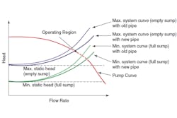
The system curve is important because the pump will operate at the flow rate where the pump curve intersects the system curve. The system curve can change based on static head changes, such as level changes between the source and destination, in open systems (see Figure 1), resulting in an operating region instead of a single point.
Net positive suction head
The net positive suction head available (NPSHA) over the range of system conditions should be determined. NPSHA is the total suction head absolute at the suction of the pump, over the vapor pressure of the liquid pumped at its operating conditions. NPSHR is a minimum NPSHA given by the manufacturer, which is required for a pump to achieve a specified performance at a specified rate of flow, speed and pump liquid.
The NPSHA to the pump will generally decrease, and the NPSHR of a pump generally increases with flow rate as shown in Figure 2.
Many pump manufacturers use an industry standard 3 percent head drop caused by cavitation (NPSH3) for published NPSHR values. This means that if a pump is operated with an NPSHA equal to its NPSH3, it is cavitating, and performance is reduced by 3 percent due to this cavitation. Unless otherwise advised, the user should assume that the published NPSHR is based on NPSH3 and provide an appropriate margin above NPSH3 as outlined in ANSI/HI 9.6.1 by market and pump type.
Centrifugal pump selection
Based on the maximum process flow requirement, select a pump or multiple parallel or series pumps that have performance curve(s) that meet the maximum requirements while operating in the pump’s POR and that have an NPSHR with sufficient margin below the NPSHA.
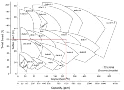
When selecting from a manufacturer’s catalog of pumps, refer to Figures 3 and 4. Figure 3 shows a selection chart or set of family curves. A selection chart shows the typical operating region for the various pump sizes for a given manufacturer’s pump type at a given rotational speed. The selection chart is useful in developing a shortlist of pumps for consideration that meets the process requirements.For example, if the previously determined maximum system requirements call for a pump running at a nominal 4-pole motor speed that could provide 1,000 gallons per minute (gpm) at 100 feet of total head, Figure 4 shows that 5 × 6 × 11 and 6 × 8 × 11 size pumps overlap on the selection chart and will likely be the two best sizes to evaluate further.
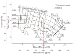
After narrowing down the appropriate pump size for the duty point of 1,000 gpm and 100 feet of head, the manufacturer’s published curves can be referenced to help determine the best pump for an application. Figure 4 shows an example of a published curve for a 5 × 6 × 11 pump running at 1,770 rpm. A significant amount of information can be derived from the manufacturer’s pump curve for this application, including the following:
- The impeller diameter that meets the rated point falls between 10 and 10.5 inches.
- The pump is 85 percent efficient at the rated point and 86 percent efficient at BEP.
- At the rated point, the pump input power will be between 25 and 30 horsepower (hp); however, to ensure a nonoverloading condition at the end of curve, a 40 hp motor may be required.
- The NPSH3 is between 9 and 10 feet at the rated point and 20 feet at the end of curve.
Note that the representations on this curve are for water at 68°F. If the specific gravity of the application liquid is higher or lower than that of water at this temperature, the power values will change accordingly. Also, if the application liquid has a higher viscosity than the test liquid, the flow, head and efficiency will need to be corrected as outlined in ANSI/HI 9.6.7 Rotodynamic Pumps — Guideline for Effects of Liquid Viscosity on Performance to select the correct pump.
As previously noted, the system may require a range of normal operating flows to meet the process requirements. The best method to control the pump to meet all normal operating points in a reliable and efficient manner should be considered. Pumps are routinely controlled to maintain process values such as level, pressure, flow or temperature. These process values can be controlled by intermittently shutting down a pump, bypassing flow, throttling flow, varying the speed of the pump or a combination of these techniques with some advantages and disadvantages of each (see Table 1).
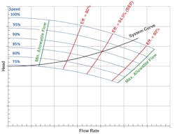
The chosen control method should consider maintaining pump operation in the POR as much as possible. Figure 5 illustrates a set of variable speed pump curves with a system curve. In this case, the 80 percent efficiency lines represent the POR. By selecting a pump at 100 percent speed where the system curve intersects the pump curve to the right of BEP, the range of speeds where operation is within the POR is maximized from 100 percent speed to nearly 80 percent speed. Also, note that when the pump speed is reduced below 80 percent speed, the pump intersection of the system curve and pump curve approaches the minimum allowable flow quickly. When using variable speed pumping as a control method, it is important to maintain minimum speed so reliability issues from low flow do not occur.
Performance testing and verification
After selecting the pump(s) and control(s) that meet system requirements, testing by the manufacturer can be specified to confirm the guaranteed hydraulic performance, the NPSH3 or mechanical integrity of the pump. The users should reference ANSI/HI 14.6 Rotodynamic Pumps for Hydraulic Performance Acceptance Tests.
Pump installation and operation
The pump should be installed per industry standards and the pump manufacturer’s installation and operation manual. The piping design should comply with ANSI/HI 9.6.6 Rotodynamic Pumps for Pump Piping Design, and the piping should be designed and aligned with the suction and discharge nozzles so that loads applied to the nozzles do not distort the pump casing and power frame. The installer can refer to ANSI/HI 9.6.2 Rotodynamic Pumps for Assessment of Applied Nozzle Loads.
Pump vibration
ANSI/HI 9.6.4 provides measurement locations and procedures for acquiring vibration data and allowable levels at those measurement levels for compliance with the standard. A properly selected, installed and controlled pump should have vibration levels within the limits set in ANSI/HI 9.6.4.
Pump vibration is related to forced vibration from mechanical or hydraulic conditions in the pump. Undesirable vibration can occur if the forcing functions (forcing frequencies) within the pump are too great or if a system’s natural frequency coincides with a forcing frequency. When a forcing frequency coincides with a natural frequency, amplification of the vibration occurs, known as resonance.
Proper design, installation and operation can ensure that forcing frequencies within the pump are low. Depending on the criticality of the pump system, known risk factors and uncertainty factors, the pump purchaser/specifier should consider specifying upfront dynamic analysis to mitigate the chances of resonant vibration. Dynamic analysis is the evaluation of forces, their frequency input to the pumping system compared to the pump system’s natural frequencies and the consequences of their interactions. As with other design and testing considerations, a cost is associated with dynamic analysis, and it should be specified accordingly. A tool for the user to consider in the specification of dynamic analysis is ANSI/HI 9.6.8 Rotodynamic Pumps — Guideline for Dynamics of Pumping Machinery. This guideline walks the user through the process so that a nonexpert could work with the manufacturer and specify the appropriate level of analysis and provide the expert doing the analysis with defined items to consider based on the sample specification contained in the document. The outcome of the dynamic analysis should be a pump that operates with installed vibration less than the allowable levels stated in ANSI/HI 9.6.4.
Conclusion
If a pump is selected to operate in its POR, the user will see reliability and energy benefits. In addition to proper selection, installation and control of the pump are also important for reliability and efficiency. Industry standards are available for the design of the pumping system and application of nozzle loads, and the manufacturer’s installation and operation manual should be followed. Dynamic analysis and performance testing can be specified to confirm that the pump will operate properly. Finally, in-field measurement of the pump vibration compared to ANSI/HI 9.6.4 can be used to verify that the installed pump vibration is not outside acceptance levels, and these values can be used to set warning and alarm levels for future monitoring.
