Historically, spills and explosions resulting from pipeline leakage have endangered human health, killed off livestock and fish, and destroyed crops and other valuable land. These types of accidents can also devastate the economic wellbeing of oil companies and the industry as a whole, in the form of costly product losses and fines as well as severe reputation damage.
In order to ensure pipeline integrity and remain in compliance with new and tougher laws, a greater number of businesses are now making the conscientious decision to install advanced leak-detection systems. These systems are capable of detecting both the presence and location of a leak, allowing a pipeline operator to address the situation quickly and effectively–before the leak can harm property or people.
A variety of leak-detection systems are currently available and corporations must thoroughly evaluate the benefits of each. A leak-detection system should demonstrate consistently high levels of sensitivity, accuracy, reliability, and robustness. It should be easy for a pipeline operator to learn, understand and use. Ideally, the pipeline integrity system should also integrate software with instrumentation in order to enhance performance and simplify maintenance.
After reviewing several recent U.S. and international laws pertaining to leak detection for pipelines, this article will take a detailed look at one innovative leak detection system and demonstrate how a Taiwanese petrochemical company put this system to good use.
New Regulations Necessitate Leak Detection for Pipeline Integrity
While some statistics indicate that the average number of hazardous liquid pipeline failures in the United States and Europe has dropped throughout the past two decades, the need for diligence on the part of oil companies will only increase in the coming years. Major leakage incidents continue to occur worldwide each year and can have severe consequences for all involved. A few recent examples include:
- In 2006, more than 150 people died after a leaking oil pipeline exploded on the outskirts of Lagos, Nigeria. Another leakage-related explosion occurred in Lagos later that same year, resulting in several hundred more deaths.
- In 2010, an oil pipeline at a pumping station in central Mexico exploded as a result of leakage and killed at least 27 people, injured 52 others and damaged more than 100 homes.
- Also in 2010, several holes in an underground pipeline led to an oil spill in Romeoville, Ill., a suburb of Chicago. More than 250,000 gallons of oil infiltrated a retention pond as well as the town’s wastewater treatment plant, causing a spike in the cost of wholesale and retail gasoline. The Romeoville incident was the second major leak of an oil pipeline owned by a particular energy corporation in a two-month span, and numerous lawsuits against the company are now pending.
As a result of occurrences like these, many governments are now taking steps to more carefully regulate the transportation of hazardous liquids and ensure that oil companies are continuously monitoring their pipelines for leaks. What follows are several examples of recommended guidelines and laws recently enacted in the U.S. and Europe.
- API 1130 (US): In 2007, the American Petroleum Institute published API 1130: Computational Pipeline Monitoring for Liquid Pipelines. Limited in scope to single-phase liquid pipelines, API 1130 is a recommended practice focusing on the design, implementation, testing and operation of computational pipeline monitoring (CPM) systems or leak-detection systems. To assist a pipeline operator in selecting the most appropriate CPM for a specific application, API 1130 defines four performance metrics: sensitivity, accuracy, reliability and robustness.
- Title 49 of the Code for Federal Regulations (US): PHMSA has developed a series of regulations governing pipeline safety known as Title 49 of the Code for Federal Regulations (Parts 190-199). While the scope of Title 49 is far-reaching, Part 195.444 makes specific reference to CPM systems, stating that any system installed on a pipeline that transports hazardous single-phase liquids must comply with the operating, maintenance, testing, recordkeeping and training guidelines set forth by API 1130.
- Technische Regel für Fernleitungsanlagen (Germany): First proposed in 2002, the Technische Regel für Fernleitungsanlagen (Technical Rule for Pipeline Systems, or TRFL) requires all new pipeline systems in Germany transporting flammable or otherwise hazardous liquids to be monitored continuously for leaks. Unlike API 1130, the TRFL does not focus on the design or implementation of leak-detection systems, but simply specifies the detection and localization functions that are required of any leak-detection system installed on a pipeline.
How the Pipeline Integrity System Works
In light of these and other regulations, installing a high-quality, leak-detection system has become a necessity for any corporation overseeing the maintenance and operation of oil pipelines.
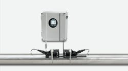
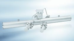
Ultrasonic leak detection is one solution. For example, an effective option is a clamp-on ultrasonic leak detection system with two or more installation points along a pipeline known as site stations, each containing an ultrasonic flowmeter, a clamp-on RTD temperature sensor, and a data communication device. The system is monitored by a master station, a computer that runs the leak-detection software and polls each of the site stations for a wide range of data. The master station uses a compensated volume balance method that continually monitors differences in flowrate between each pipeline segment (the portion of the pipeline bounded by two site stations) and compares a one-minute rolling average over intervals of 1, 5, 15 and 60 minutes. If the line balance deviates by more than a pre-established threshold, a product release alarm will sound.
In the event of a leak, a low-pressure wave (or pressure transient) is generated and radiates both upstream and downstream from the leak location at the speed of sound for the particular liquid flowing through the pipe. This drop in pressure will cause a decrease in the density of the liquid, thereby decreasing the liquid’s sonic propagation velocity (Vs) as well. As the site stations along the pipeline process Vs approximately 80 times per second, this sudden decrease will be detected and time-stamped by each station. The master station can then determine the location of the leak by calculating the relative difference in arrival time of the pressure transient at each site station. For example, if the pressure transient arrived at both site stations at exactly the same time, the leak must have originated at the middle point of the monitored segment.
CASE STUDY: Taiwanese Petrochemical Company Employ Pipeline Integrity System
The GUI AdvantageOlder leak detection software often utilizes an MS-DOS environment and displays site stations as square boxes. However, the location of these stations on the screen does not accurately represent the layout of the application being monitored. Instead, the software displays the stations in a straight line and labels them with unique identification numbers. It is the pipeline operator’s responsibility to match these numbers with the individual stations they represent. As a result, a significant amount of operator training is required, and it may still prove difficult to pinpoint the location of a leak in the event of an alarm. In a worst-case scenario, it can even become necessary to shut down the entire pipeline in order to isolate the problem area.
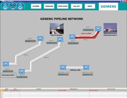
The Siemens leak detection software features a new graphic user interface that allows a pipeline operator to visually identify pipeline locations on a map and easily pinpoint leak locations.
On the other hand, the Siemens leak-detection software features an enhanced graphic user interface (GUI) that allows for rapid identification of key locations along a pipeline. Site stations and the pipeline segments that connect them are laid out accurately in a map format, making it very easy for the operator to see the true location of an alarm and shut down only the affected segment. It is even possible to customize the software with photos of the actual site to make it as realistic as possible. Thanks to this new software, much less operator training is required and response times to potential leak situations may be drastically reduced.
A petrochemical company in Taiwan sought a replacement for their existing leak-detection system, which had not been functioning properly for quite some time. The faulty system was installed on a 50 km segment of a 181 km underground pipeline carrying various hydrocarbon products. Before determining which vendors could participate in a large project bid, the company required that interested contenders (including Siemens) participate in a weeklong on-site test of their leak-detection solutions. The company had three basic requirements in choosing a new system: accurate detection of accidental product release, accurate determination of product release location, and the ability to identify pipeline product theft. The third requirement was the most challenging, as theft generally occurs at exceedingly low rates of flow for short periods of time. Therefore, the winning system would need to demonstrate a high enough level of sensitivity to detect even the smallest of pressure transients.
The testing segment provided by the petrochemical company (Figure 1) comprised 119 km of a single underground pipeline that transported diesel oil at flowrates ranging from 0-300 m3/h. To participate in the test, Siemens installed three clamp-on ultrasonic flowmeters (labeled A, B and C) along the pipeline with an Ethernet connection between each meter, and one master station with its own Ethernet connection in the control room. Two segments (A-B and B-C) were monitored for leak detection and leak location. The distance between A and B was 55 km, and between B and C was 64 km.
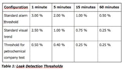
Based on the petrochemical company’s operating conditions, Siemens set up four different leak thresholds for the leak-detection test (Table 1).
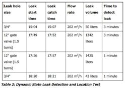
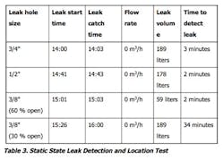
To conduct the test, the petrochemical company randomly simulated leaks of various sizes by opening the ball valves and gate valves at differing levels and speeds. The company was particularly interested in the performance of the leak-detection system when the gate valves were opened slowly, as this action might generate a pressure transient too small for less sensitive systems to detect. The tests were conducted at dynamic flow state one day (Table 2) and at static flow state the next day (Table 3).
The Siemens leak-detection system was able to detect product release and location at both dynamic and static flow states with similarly high accuracies.
Frank Fromm is an International Business Development Manager for Siemens clamp-on ultrasonic flowmeters based in Hauppauge, NY. He is responsible for providing both domestic and international support for all of the flow products in the SITRANS FUS1010 family, with a focus on the oil & gas industry. Mr. Fromm also has a product development background with the SITRANS FUT1010 spool flowmeter and the Siemens leak detection system. He can be reached at [email protected].
www.siemens.com/flow


