To better understand the whys and wherefores of leak detection and repair, or LDAR, it is useful to briefly review the relevant regulatory history. These programs have their genesis in the Air Pollution Control Act of 1955, which evolved into the Clean Air Act of 1963 and was amended in 1970 to include vehicle emissions. The latter was further amended in 1990 to include LDAR programs for petroleum refineries and chemical processing plants emitting volatile organic compounds (VOCs) and hazardous air pollutants (HAPs) from leaking valves, pumps and compressors, tanks and flanged piping, and equipment connections.
Evolution of Enhanced LDAR
By the late 1990s, the U.S. Environmental Protection Agency determined refineries were under-reporting emissions by a significant amount, thus indicating that LDAR programs were not achieving the desired results. As such, a need was identified for enhanced programs that proactively seek out and eliminate leaks. Between 1998 and 2008, non-compliant facilities were required to institute formal LDAR programs with dedicated management. Today they are required to implement enhanced LDAR programs that call for the use of certified low-leak valves and sealing technologies.
Enhanced LDAR programs are defined by directives in consent decrees, which indicate the equipment and components to be monitored, leak criteria and remediation, and documentation and reporting. These programs consist of multiple elements, including general applicability; monitoring frequency, methods and equipment; action thresholds; leak repairs; delay of repair; equipment upgrades, replacement and improvement; change management; training; quality assurance and control; LDAR audits and corrective actions; certification of compliance; recordkeeping; and reporting.
The focus of the following discussion will be the element of equipment upgrades. It should be noted the requirements of Enhanced LDAR are in addition to, not in lieu of, existing local, state and federal regulations. In the event of conflicts, the more stringent requirements prevail.
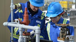
Monitoring requires the use of Method 21, with a toxic vapor analyzer and data logger, and varies with the type of equipment – monthly for pumps and agitators, quarterly for valves and closure devices on open-ended lines, and annually for piping and equipment connectors (Figure 1). Levels of leakage requiring remedial action also vary – 250 PPM for valves, closure devices and connectors, 500 PPM for pumps, and 2,000 PPM for agitators. To quickly detect large leaks well in excess of allowable levels, the EPA adopted the Alternative Work Practice, which employs optical imaging technology such as handheld infrared cameras that allow users to see fugitive emissions (Figure 2). However, this technology does not quantify leaks, so annual Method 21 surveys are still required.
Initial attempts to repair such leaks must be made within five days of detection, and final attempts within 15 days. If a component cannot be immediately repaired or removed from service, it may be put on a delay-of-repair list subject to EPA inspections.
Equipment Factors
As noted, Enhanced LDAR programs also mandate equipment upgrades, replacement and improvement. With these requirements comes a dramatic reduction in acceptable emission levels from 500 PPM under conventional LDAR to 100 PPM under Enhanced LDAR. The EPA mandates alternatives for meeting these requirements. One, though yet to be prescribed in a consent decree, calls for preventive maintenance and replacement, which in turn requires trend analysis of leaking components. Depending on their rates of leakage, components can be technically in compliance and still targeted for repair or replacement.
All consent decrees to date that demand Enhanced LDAR require the use of low-leak valve and low-leak packing technologies warranted not to leak above 100 PPM for five years. Note, it is important to consult with the manufacturers regarding these warranties as they are subject to valve conditions and installation.
If not warranted, these technologies may be tested and documented using a number of generally accepted methods for identifying leak performance. Test methods include ISO 15848-1 for industrial valves; API 622 for process valve packing; Chevron Texaco GR-500 App. V for packing refinery equipment; Shell MESC SPE 77/300 type-acceptance test for industrial valves; ISA/ANSI 93.00.01 for external leakage of on-off valves; FCI 91-1-1997 for control valve stem seals; VDI 2440 for mineral oil refineries. Additional methods are published by TA Luft and others.
Enhanced LDAR calls for valve stem packings leaking in excess of 250 PPM to be replaced with low-leak technology within 30 days or at the next scheduled maintenance outage. If leaking between 100 PPM and 250 PPM, they must be repaired or repacked annually per the following equation: VTBRR = 0.10 x (VT -VDOR -VPRR -VPR) where VTBRR is valves to be replaced or repacked annually, VT is total number of valves in the facility, VDOR is valves on delay of repair, VPR is valves pending repair and VPRR is valves previously replaced or repacked with low-leak technology. Depending upon the severity of a facility’s fugitive emissions, the EPA may require 20 percent rather than 10 percent of the qualified valve population to be replaced or repaired.
Enhanced LDAR programs also address leaking flanged, threaded, compression, cam-lock and quick-connect connectors. These components do not require warranties and test reports, but like valves are subject to repair and replacement. Connectors found to be leaking at or above 250 PPM must be brought under 250 PPM within 30 days of detection. Leaking connectors can also be remediated by replacing them with welded joints or piping.
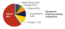
Under consent decrees prescribing Enhanced LDAR programs, cited facilities must report all such equipment repairs, replacements and eliminations, including identification of relevant components, corrective actions for compliance and scheduling for future upgrades and replacement. Because leaking valves are estimated to account for 60 percent of fugitive emissions from refineries and chemical plants, the balance of this discussion will be devoted to bringing and keeping them in compliance with the requirements of Enhanced LDAR (Figure 3).
Low-Leak Technologies
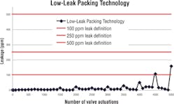
Figure 4. Typical data from a low-leak packing test report.
Fugitive emissions from leaking valve stems can be controlled by following simple guidelines that take into account the valves and their service conditions, sealing suppliers’ recommendations, proper installation, and performance monitoring. To avoid leaks in the first place, the EPA encourages the use of low-leak technologies, notably low-leak valve stem compression packing (Figure 4).
Determining the most-effective packing solution depends on a number of variables, such as the mechanical condition of the valve. Damaged gland studs and bent or gouged valve stems can adversely affect the compression of the packing rings, pushing and tearing into them and rendering them incapable of sealing effectively.
Other factors to consider include whether the valve is actuated occasionally or continuously, the operating conditions to which it will be subjected – such as temperature, media and pressure, and the level of performance required to meet federal, state and local regulations.
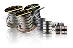
Graphitic valve stem packings typically provide the best VOC/HAP leak performance. Die-formed, flexible graphite packing with braided carbon yarn end-rings has been used for more than 30 years to provide 500 PPM leak performance, well above the level demanded by some regulatory agencies and end-users. However, engineered, die-formed graphite sets and the latest developments in braided flexible graphite packing are capable of <100 PPM performance (Figure 5). The latest braids can withstand temperatures up to 850 F (454 C) in atmosphere, 1,200 F (649 C) in steam, and pressures up to 4,000-plus PSIG. In addition, braided packing is convenient for field repacking of valves.
Also capable of providing <100 PPM performance are engineered sets, which are sized for specific valve and packing box dimensions. These sets combine die-formed and braided graphite packings. As such, they offer the same temperature capabilities, but a substantially higher pressure rating, i.e., 10,000 PSIG. The die-formed graphite rings vary in density and geometry, resulting in low emission capability, valve actuation force and stem friction, and high radial expansion under compression, seal retention, and adjustability. Valve manufacturers prefer engineered sets due to their low-emission performance and speed of installation during the assembly process.
Most recently, advanced technology spool packing capable of as low as 20 PPM leak performance has been developed. Designed for use in the hydrocarbon and chemical processing industries, it combines two different types of braided flexible graphite for on-site creation of ultra-low-emission packing sets. The new packing can withstand temperatures from -328 F (-200 C) to 1,200 F (650 C) in steam and non-oxidizing environments and up to 850 F (455 C) in media containing free oxygen. Maximum pressure rating is 4,500 PSIG (310 bar)
Mechanical Solutions
Valve stems can also be sealed by means of mechanical solutions, such as metal bellows seals and live loading. In the former a metal bellows seal is incorporated into the valve design with packing serving as a secondary seal. Bellows-sealed valves are capable of virtually zero emissions, but they are considerably more costly and require more space than standard packed valves, and if the bellows fail, the valves must be rebuilt or replaced.
Temperature and pressure ratings vary with the metallurgy, design and construction of the bellows and should be specified to match the pressure class and material rating of the valve.
Live loading involves the use of disc spring, or Belleville, washers, which are compressed on the valve gland follower under the gland stud nuts to enhance consolidation of the packing for longer and better seal performance. It can be used to enhance the performance of any packed valve subject to numerous actuations or thermal cycles, and is a good solution for valves that are difficult to monitor and adjust.
Sealing Installation
Just as important as selecting the correct type of sealing is assuring that it is installed properly, which will both enhance its emissions performance and extend its service life. Begin by removing the old packing, inspecting the stem and stuffing box, and repairing or replacing worn or damaged components. As noted, valve condition plays an important role in sealing performance and longevity. A valve with a bent stem, for example, will maintain low emission levels until it is actuated, after which it will become a chronic leaker. Moreover, installing new packing in a worn valve may invalidate the manufacturer’s performance warranty. Required under Enhanced LDAR, these warranties are subject to the physical condition of the valve, the conditions in which it operates, and adherence to the manufacturer’s installation instructions.
With regard to packing installation, the valve stem and bore diameter should be measured, as well as the depth of the stuffing box to assure the correct packing size and number of rings to be used. Braided packing should be cut to size and installed one ring at a time. Die-formed packing is susceptible to breakage, so it too must be installed carefully. Instructions for installing engineered sets are provided by the manufacturers, and must be followed assiduously to assure proper performance and warranty maintenance. After installation and proper compression of the packing, a valve can be actuated, adjusted and monitored for performance.
The New Norm
Dramatically lower emission levels and proactive efforts to attain and maintain them put the enhanced in Enhanced LDAR. Employing low-leak valve technology and replacing 10 percent, or alternatively 20 percent, of a facility’s qualified valve population leaking between 100 PPM and 250 PPM are mandated to bring all regulated components under the 250 PPM screening value. Enhanced LDAR establishes 100 PPM as the new emissions standard for valve stem seals.
This new norm puts even greater performance demands on valve stem compression packing, which is still the most cost-effective solution to controlling fugitive emissions. Meeting these demands requires diligence in selecting and installing packing, ideally involving sealing and valve manufacturers, installers, end-users and regulators.
James Drago, P.E., has worked in sealing technology for over 25 years, most recently for Garlock Sealing Technologies. His work has focused on applications, product engineering, engineering management, and global business development. He has authored numerous articles and presented papers at technical symposia on sealing to meet fugitive emissions regulations and sealing product selection. He also has contributed to the industry standards of the American Petroleum Institute (API), American Society of Mechanical Engineers (ASME), Electric Power Research Institute (EPRI), and Society of Tribologists and Lubrication Engineers (STLE). He earned a bachelor’s degree in mechanical engineering from Clarkson University (formerly Clarkson College of Technology) and is registered as a professional engineer in the state of New York. He can be reached at [email protected].
