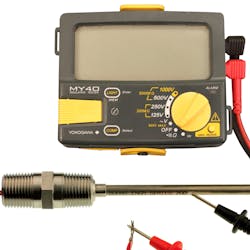
The platinum resistance thermometer (PRT) is one of the most widely used temperature sensors for control and monitoring of manufacturing processes. High accuracy, repeatability and long-term stability over a wide temperature range are reasons PRTs are so popular.
Like any measurement instrument, they may experience changes that affect their accuracy and that can lead to a process that is out-of-control. Performing a periodic calibration or verification is necessary to monitor the PRT performance and predict possible future replacement. Two of the most important checks to make are the insulation resistance (IR) and ice point resistance (R0).
Insulation resistance (IR)
Before performing either a verification or calibration test, an insulation resistance test should be performed to ensure that the sensor is free of moisture or other contaminants that can affect performance. Using a megohmmeter, touch one lead to the probe sheath and the other to the lead wires. Set the meter to 50 VDC or 100 VDC, and the resistance should be at least 200 megohms at room temperature. Many manufacturers perform this test at 100 VDC and 500 megohms as the acceptable range. Low insulation resistance can cause a lower than actual temperature sensed by the PRT. For example, at 100k ohm, the error is about -0.25°C. Low IR can also cause the probe to be unstable and not repeatable.
Verification
Verification is a check of the PRT resistance at a known temperature, usually at 0°C in an ice bath, to see if it meets either of the two PRT standards, ASTM E1137 or IEC 60751, interchangeability tolerances. The test can be performed in a lab but is more commonly done in the field using an ice bath or by comparison to a temperature standard while immersed in a constant temperature bath.
The easiest and most accurate test is performed using an ice bath and an ohmmeter. Accuracy of 0.05°C or better can be achieved with an ice bath provided it is made up correctly. Use ice made from distilled or purified water and crush it to about 1/4-inch pieces, pack it into an insulated container and then top off with just enough distilled water to fill in the gaps without having the ice float. Then, insert the PRT about 4 to 6 inches, connect the ohmmeter and wait for the reading to stabilize. This may take a few minutes for everything to equilibrate.
If your meter has a three- or four-wire resistance input capability for eliminating the lead resistance, then you can read the measurement directly from the display. If not, then you will need to make two measurements to manually compensate for lead resistance. PRTs will have either three or four wires with color codes of red and white. Typically, there are two red leads connected to one side of the PRT resistor and the white lead(s) to the other. First, measure resistance in the red leads and then measure the resistance between one of the red leads and a white lead. Subtract the red leads measurement from the red and white measurement, and you are left with a very close approximation of the resistance of the PRT sensing element, and that is the number you will compare to the standards.
The interchangeability tolerances are what the PRT manufacturers strive to meet. They can be shown graphically as shown in Figure 3. Note that the IEC tolerances are wider than the ASTM tolerances and that they grow as the temperature moves away from 0°C.
There are equations that will calculate the interchangeability tolerance at any temperature for each of the grades or classes of PRT. You will need to know which of the tolerance bands your PRT manufactured to know if it falls within the original tolerance band.
These equations are:
ASTM E1137 Grade A ± [0.13 + 0.0017 | t | ] °C
ASTM E1137 Grade B ± [0.25 + 0.0042 | t | ] °C
IEC 60751 Class AA ± [0.10 + 0.0017 | t | ] °C
IEC 60751 Class A ± [0.15 + 0.0020 | t | ] °C
IEC 60751 Class B ± [0.30 + 0.0050 | t | ] °C
IEC 60751 Class C ± [0.60 + 0.0100 | t | ] °C
Note 1: | t | = absolute value of temperature of interest in °C
For example, at -50°C for a PRT that was manufactured to the IEC 60751 Class A, the interchangeability tolerance is: ± 0.15 + 0.0020 (50) = ± 0.25°C
Calibration
Calibration is performed to verify sensor performance over a wide temperature range and characterize the R versus T relationship.
When we think of calibration, it usually involves adjustment of the instrument. However, there is no adjustment to an RTD, therefore, it is a characterization of the sensor resistance at any given temperature.
A key feature of a calibration is that it establishes traceability of the measurement to national or international standards.
Calibration is usually performed in a lab using high accuracy measuring equipment that is at least four times more accurate than the device being tested. Tests are performed by comparison to a temperature standard immersed in a constant temperature bath along with the test units. A data acquisition system collects the resistance readings and software outputs a report. Manufacturers of this equipment offer turnkey packages, or you may opt for a custom system consisting of components from various manufacturers.
A typical setup for a comparison is shown in Figure 4. The cost of these systems vary based on your desired accuracy.
Frequency
This information about verification and calibration is great, but how often should I perform either of these tests? This is one of the more difficult questions to answer. It all depends on your process and your confidence level in the measurement.
There are several factors to consider:
- New plant or equipment commissioning. Performed to verify manufacturer test and performance data. Shipping and installation damage can occur or rarely a PRT may be defective.
- Establish and record initial performance as a baseline to show trends for predictive maintenance. This may be as simple as an IR and ice point resistance check.
- Manufacturer recommendations.
- Process characteristics can have a large influence on the long-term repeatability and stability of the PRT. High vibration and/or temperature cycling will cause the PRT to drift over time.
- Third-party audit requirement may specify a minimum frequency.
- Safety. Overheated process may cause a fire or explosion.
- After an event such as a lightning strike or equipment repair.
- Before and/or after a critical measurement or batch process. A batch process for a high-value product may require a calibration or verification before and after to ensure that the sensor remained accurate throughout the process.
Summary
Periodic calibration or verification of performance is necessary to maintain the measurement accuracy of your process. Frequency is determined by the process characteristics, product value or safety concerns. Vibration, mechanical shock, temperature cycling or time near maximum temperature may cause the PRT to drift slowly. A simple verification test in an ice bath is the best method to track performance and set future recheck intervals. Completing five verification or calibration cycles without a shift in performance allows for doubling the time between checks. Following these guidelines will ensure accurate and repeatable output from your PRTs and keep your process in control.
Bill Bergquist is principal applications engineer and RTDologist at Burns Engineering with 37 years of experience in temperature measurement with RTDs and thermocouples in the aerospace, industrial and laboratory markets.


