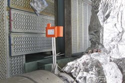
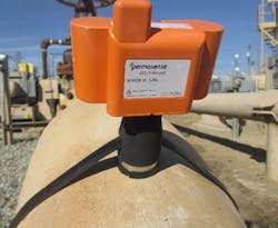
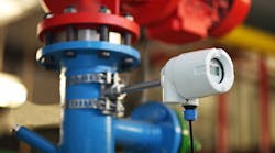
Online corrosion and erosion monitoring systems (see Image 1) are fast becoming an industry best practice for oil and gas facilities, refineries and chemical plants. The right monitoring system will deliver quality measurements in real time to the desks of those who need the information. The wrong system will deliver useless measurements, require extensive training and expertise to install or operate, need extensive maintenance, or fail in service.
According to a National Association of Corrosion Engineers International study, “The global cost of corrosion is estimated to be US$2.5 trillion, which was equivalent to 3.4 percent of the global GDP in 2013. By using available corrosion control practices, it is estimated that savings of between 15 and 35 percent of the cost of corrosion could be realized; i.e., between US$375 and $875 billion annually on a global basis.
“These costs typically do not include individual safety or environmental consequences. Through near misses, incidents, forced shutdowns (outages), accidents, etc., several industries have come to realize that lack of corrosion management can be extremely costly and that, through proper corrosion management, significant cost savings can be achieved over the lifetime of an asset. To achieve the full extent of these savings, corrosion management and its integration into an organization’s management system must be accomplished by implementing a Corrosion Management System…”
Two main types of corrosion monitoring systems are available: traditional inline probes that place a sacrificial element that deteriorates from corrosion inside the process fluid, and ultrasonic systems that measure wall thickness.
Inline probes require a hole to be made in the side of the piping/vessel so the probe can be placed in contact with the fluid. This access fitting is often specified when the plant is built. Inline probes measure the damage to a sacrificial element of the device, from which the damage occurring to the actual equipment wall is inferred.
Although inline probes work well in many applications, this article focuses on nonintrusive ultrasonic systems to help engineers specify the best nonintrusive corrosion or erosion monitoring systems for their applications.
Measurement quality
For monitoring purposes, the ability to continuously detect and measure wall thickness loss with a high degree of repeatability is generally more important than the absolute accuracy of a single measurement. Some vendors quote resolution and accuracy without supporting data from the field. Other vendors quote resolution as the number of decimal places the thickness measurement is capable of under ideal conditions. And some vendors quote results from data collected under controlled laboratory conditions, which is generally not achievable under real field conditions.
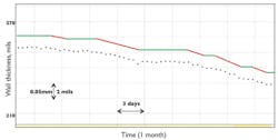
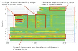
Ask to see real field data (see Figure 1) where wall loss has been detected to determine how small a metal loss is measurable, and how quickly that loss can be recognized from the measurement data.
Also ask to see real field experience that shows measurement quality will not degrade over time; for example, piezoelectric transducers in permanent contact with hot metalwork age and introduce distortion into signals. Transducers that require a coupler or are glued onto the metalwork will also likely degrade over time in industrial applications.
Internal surface roughness
Certain corrosion mechanisms — such as microbial attack, napthenic acid corrosion or sulfidation corrosion — create rough or pitted internal surfaces. Standard ultrasonic wall thickness measurements are extremely sensitive to internal surface roughness, which can negatively impact accuracy. Issues arise when this noise effect masks wall thickness loss or when this noise effect shows an apparent thickness increase.
Some vendors have researched this effect in detail and engineered proprietary signal processing that compensates for the effects of internal surface roughness on wall thickness measurements. These advanced and patented signal processing methods take advantage of the historical data delivered by the sensor to adapt and deliver wall thickness measurements immune to the effects of internal surface roughness.
This makes the measurements provided more timely and easier to interpret since an understanding of ultrasonic physics is not required to make sense of the data or derive value from it. This leaves time for the engineers to instead extract value from the data by making better-informed operational decisions about an asset.
Micro-changes in the internal surface condition of a pipe or vessel can be used to detect the onset of corrosion before any wall loss occurs. Look for systems that offer this advanced detection capability because it will deliver the capability to detect very small corrosion or erosion events. Users of these systems have reported that these micro-changes in internal surface condition correlate with extremely small changes in the underlying corrosion-causing variables in a refinery, such as total acid number and sulfur content of the processed crudes (see Reference 3).
Compensation for other field variables
Corrosion and erosion monitoring systems are often negatively affected by other process variables, which can add noise to the measurements. For example, electrical measurements can be significantly affected by temperature. Electrical resistance measurements can also be affected by the electrical conductance of the fluid in the pipe or vessel. Ultrasonic wall thickness measurements are affected by the pipe material since this impacts the speed at which the ultrasound travels in the metal being measured.
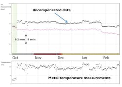
Look for systems that can factor out these variables to make the data more reliable and easier to understand. In particular, the metal temperature must be measured by the sensor at each measurement point at the same time as each ultrasonic wall thickness measurement is acquired to reliably compensate wall thickness measurements (see Figure 2).
Hazardous area requirements
Most oil and gas facilities have areas zoned as hazardous because of flammable gases and vapors in the local environment that could be ignited under certain conditions.
Consider the desired monitoring locations and the associated hazardous area rating. Some vendors use the explosion-proof protection concept, which cannot be installed in some hazardous areas. Instead, it is better to use devices designed as intrinsically safe, which are certified for installation in the most hazardous of locations (Zone 0 and Class 1, Division 1).
Hazardous area classifications can change over time and have become more stringent in the past 10 years. Systems designed for use in Zone 0 and Class 1, Division 1 areas are future-proofed against these types of changes.
Temperature conditions
Different parts of the facility will likely operate at a range of temperatures. In addition, sometimes the temperature of the equipment in a given location deviates substantially from the design temperature — for example, when steam-cleaning the equipment. It is important that the monitoring equipment can handle any temperature at which the location will operate to avoid damage to the monitoring equipment or loss of measurement integrity.
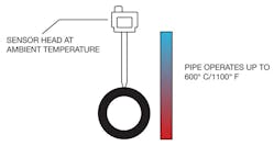
The monitoring device must also be able to withstand severe surface temperatures of the pipe or vessel where it is mounted (see Figure 3).
Ask the vendor for field references proving the monitoring equipment will continue to function through the range of temperatures of interest. Do not rely on laboratory tests that show only short-term robustness.
Installation flexibility
Look for monitoring equipment that can be installed across a wide range of locations and operating conditions. For example, devices that can be installed in Zone 0 hazardous areas can be installed in any hazardous area. Devices that cover the full range of operating temperatures will present fewer logistical challenges than those that only work in a small subset of operating temperatures.
Specify devices that can be installed on a full range of pipe sizes and vessels (see Image 2), ideally without the need for custom-made mounting solutions for each location. Systems that provide their own data retrieval infrastructure (for example, WirelessHART) require fewer prechecks of infrastructure availability than cellular data retrieval, for example, which will only function in areas with good cellular coverage.
Factor in the installation costs of the monitoring equipment. For nonintrusive ultrasonic systems, the primary installation costs will be associated with gaining access to the desired locations. Look for systems that do not require cabling in the hazardous area — for example, between transducers and associated electronics equipment — since this will greatly increase the installation and maintenance costs because cables are likely to be damaged in service over time.
Specify a monitoring system that requires minimal maintenance and infrequent battery replacement. In addition, look for systems in which the battery can be replaced in hazardous areas without the need for hot work permits to save time and money when carrying out this field maintenance.
Displaying the data
A monitoring system will deliver its highest value if users can:
- View real-time data from their desks
- Quickly visualize, analyze and understand the data
- Use the data to inform operational decisions
Avoid monitoring systems in which the data must be sent away for interpretation off-site since this will incur delays and likely an additional interpretation/processing fee.
Specify a system where real-time measurements and historical measurements are available for viewing and analysis in an easy-to-use data management interface. Systems that offer browser-based data viewing are more flexible than those that require a software program to be installed on each user’s computer. The latter may also have complicated license agreements.
Look for visualization software platforms designed specifically for the data being delivered instead of general purpose software. Features such as corrosion rate analysis and classification, multisensor data plotting and report generation make the data easier to integrate into daily operations, and should therefore be included (see Figure 4).
Data retrieval method
Various methods are available to retrieve the data from corrosion monitoring sensors, including:
- Cabled (4-20mA, Modbus, etc.) into the control system
- Industrial wireless (WirelessHART, etc.)
- Cellular/GSM communication
- Satellite communications
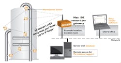
Cabling is extremely expensive, especially in hazardous areas. Wireless data retrieval from the field devices is the preferred solution for monitoring applications. Industrial wireless mesh protocols such as WirelessHART (see Figure 5) are widely accepted as best practice for monitoring systems data retrieval.
With WirelessHART and other similar industrial wireless networks, no additional data retrieval costs exist once the system has been installed, and no radio license is required. In addition, the creation of a wireless mesh network — in which the monitoring devices communicate and relay information among themselves and the gateway — offers extremely robust data retrieval in industrial processing environments, even when line-of-sight among all measurement devices and gateways is not possible.
Cellular communication is only possible where good coverage exists. Data retrieval requires an ongoing expense that must be factored into the system life cycle cost. In addition, different sites will require cellular data contracts with different suppliers, creating logistical management challenges.
Satellite communication offers more flexibility and near-global coverage. Satellite backhaul is especially useful when no IT infrastructure exists to tap into, such as on older, unmanned oil and gas production platforms. Satellite communication equipment costs can be expensive, so specify a system that does not require a satellite communication link for each sensor, but instead can group sensor data. Satellite communication will incur an ongoing cost. Look for vendors that can manage this subscription as part of their offerings.
Own the data
Ideally, the monitoring system’s database will reside on one’s own server, rather than on a vendor’s server. If choosing to use the vendor’s servers and databases, then insist on retaining ownership of the data, and ensure the vendor has appropriate data security measures in place.
Hosting the monitoring system database on one’s own server makes it considerably more straightforward to export this data to process historians, asset management systems and other applications. Combining corrosion and erosion monitoring data with other recorded process data can offer valuable insights into the root causes of corrosion or erosion events that occur in a facility.
If leveraging existing cabled information technology (IT) infrastructure to link the field gateways and the system user (data consumer) is not desired, or if the infrastructure does not exist, then an Industrial Internet of Things installation can be an attractive option. In this configuration, the field hardware (sensors and gateways) are as shown in Figure 4, but instead of one’s own IT infrastructure, cellular modems are used to send the data to secure servers in the cloud.
This facilitates data viewing and analysis from anywhere with an internet connection (subject, of course, to secure login), and means the monitoring system can be installed and used without any need to interact with existing IT/control systems. This option can be extremely attractive for remote locations without existing IT infrastructure, such as unmanned platforms and onshore oil and gas production wellheads.
Summary
When specifying a continuous corrosion monitoring system, make sure the vendor can provide evidence that the monitoring system will work in the operation. Do not rely on laboratory tests or unsubstantiated promises. Field experience from similar installations is critical for gaining the required confidence that the monitoring system will work over a period of many years in the environment.
Look for a system that requires minimal maintenance, is easy and inexpensive to install, and delivers the quality and frequency of data needed. This will result in improved operations and increased profitability.
References
- Non-Intrusive Corrosion and Erosion Monitoring: https://www.emersonprocessxperts.com/2017/02/non-intrusive-corrosion-erosion-monitoring/
- Wireless and Continuous Corrosion Monitoring: https://www.emersonprocessxperts.com/2017/07/wireless-continuous-corrosion-monitoring/
- About the Correlation Between Crude Oil Corrosiveness and Results from Corrosion Monitoring in an Oil Refinery: http://corrosionjournal.org/doi/pdf/10.5006/1940?code=nace-prem-site
Jake Davies is marketing director for Emerson‘s Permasense corrosion technologies. He has been involved in the development, deployment and support of corrosion and erosion monitoring systems since 2008, when Permasense was first formed. Davies holds a doctorate from Imperial College London, a Master of Engineering from Oxford University and an MBA from The Open University. Find him on LinkedIn at linkedin.com/in/jake-davies-26665a19.
