You said before I met you, your life was mighty tame
I took you to a nightclub, the whole band knew your name!
— "I’ve Got News For You," by Ray Charles
The way we’ve always done it
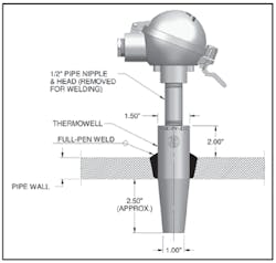
The humble thermowell is as simple as it gets, right? A simple piece of bar stock machined to intrude into piping and house a temperature sensor. Companies have been building power plants, HRSGs, boilers, and heat exchangers with well-established in-house practices that have been around for years. So why rock the boat, right? This is the way we’ve always done it. Why worry about steam cleanout?
If that is the way you tend to think about thermowell design, and you are involved with piping and thermowells that are exposed to steam cleanout, then as the old Ray Charles song goes, "I’ve got news for you."
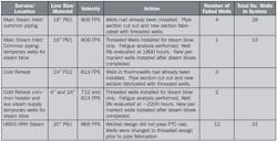
If your thermowells are welded into place and are exposed to steam cleanout, some of them likely do not pass the new ASME Thermowell standard (Table 1).
Why steam cleanout impacts thermowell design
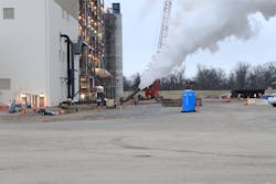
First, for those wondering what steam cleanout is, here’s a bit of background. Prior to startup of a new steam power plant "steam blow" or "steam cleanout" occurs. In the course of this process, the steam piping is disconnected from the turbine. The boilers are fired, and steam is channeled at extremely high velocities to cleanout the pipes. This ensures that no debris is left in the piping upstream of the turbine. It is, of course, very important that there is no debris upstream of the shiny new turbine that could cause damage to its blades in operation. For that reason, steam cleanout is a routine part of every new plant startup, as well as for turn-arounds that impact upstream piping.
In the course of steam cleanout there is minimal need for extensive temperature monitoring, other than the few required temperature measurements obtained to assure that steam blow conditions are being adequately maintained. The event is short lived with total durations on the order of 20 hours or so. So, you may be thinking why are thermowells a concern in this instance?
READ ALSO: Solving Erosion-Related Thermowell Failures—Lessons learned from a coal pulverizing line
The power piping upstream of a turbine typically arrives on site with thermowells already welded into the pipe. In the operation of a plant, thermowells in these steam lines can be subjected to extremely high operational velocities, often in excess of 150 ft/sec, and sometimes in the neighborhood of 200 ft/sec to 300 ft/sec. However, during steam cleanout, these same thermowells are often subjected to velocities in excess of 600 ft/sec — sometimes in excess of 1,000 ft/sec for several hours.
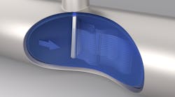
A quick refresher may be in order to explain why high-velocity steam can be bad for thermowells. In a nutshell, as steam passes the shank of an installed thermowell it causes the thermowell to vibrate. At certain high velocities the thermowell vibration can begin to "resonate" (i.e., shake violently) when the natural frequency of the thermowell assumes a specific ratio to the frequency of the vortices being shed in the thermowell’s wake — hence the term "wake frequency."
This phenomenon is known in scientific circles as the Von Karman Effect and has been responsible for the catastrophic destruction of cooling towers, suspension bridges, and the humble thermowell. In the 1970s, the persistence of thermowell failures in power piping due to this phenomenon became so acute that the ASME issued a thermowell calculation in the PTC 19.3 standard, providing a calculation to evaluate the likelihood of failure. In 2010, this standard was revised as the ASME 19.3TW standard in response to field reports of thermowell failures not caught by the earlier 19.3 methods. The result of the new standard has yielded a design threshold that is significantly more conservative than in times past.1 The aim of the 19.3TW calculation is to design the thermowell so that resonance is avoided where at all possible to prevent fracture or fatigue to the thermowell shank.
The end result is that due to the more conservative nature of the 19.3TW standard it is almost impossible to achieve a passing result in steam cleanout conditions at velocities in excess of ≈ 650 ft/sec.
Do I really have to apply steam cleanout conditions to thermowells per ASME 19.3TW?
The thermowell standard does not accommodate all thermowell designs. One could design a thermowell to be outside the scope of the thermowell standard by using a tip-to-root ratio that is less than 0.58, or by using a U-length that is less than 2.5", and then claim that 19.3TW is not applicable. One could also argue that 19.3TW is not specifically mandated by B31.1 and so is not applicable to the application. However, good engineering practice mandates that some basis be used for the design of these components.
This is what ASME 19.3TW has to say about steam blow:
In all cases, design calculations shall take into account the possibility of flow increases above the design rating of the mechanical equipment and for process upset conditions. Specific flow conditions should be used where such data are available. Examples include start-up, shutdown, process upset, and pressure-relief conditions. Pre-startup conditions, such as steam blows for pipe cleanout shall also be considered. In the case of high-pressure steam blows, the fluid velocities can greatly exceed 100 m/s (300 ft/sec), and the thermowells shall be designed for these conditions. – ASME/ANSI PTC 19.3TW (2010), Section 6-3.3.
In the event of a thermowell failure due to fatigue incurred by steam blow, one would be stuck facing the question of why the choice was made not to apply the 19.3TW standard to that thermowell. One could go to the end-user/owner and ask for a specific exception in the case of these thermowells. However, that does not establish a design basis.
Along these lines, the standard also states:
The designer of [the system that incorporates the thermowell] is also responsible for ensuring the thermowell is compatible with the process fluid and with the design of the thermowell installation in the system. – ASME/ANSI PTC 19.3TW (2010), Section 9-1.
The "designer of the system that incorporates the thermowell," of course, means engineering companies and OEM manufacturers of power plant equipment that incorporates power piping.
Other design basis methods might be acceptable, such as relying on empirical data/past practices, provided those can be documented adequately … not an easy chore. Numerical methods can also be used, provided the designer has the resources and project schedule to implement them effectively. Neither of these tend to be economically desirable for a low-cost mundane component like the lowly thermowell.
Garbage in, garbage out — The danger of designing based on cleanout process conditions provided a year before commissioning
One more wrinkle: How reliable are process conditions for steam blow that are provided a year or more prior to commissioning?
Even if one could design all of the welded thermowells so that they passed muster, applying the process conditions known at the time of a thermowell purchase is a notoriously unreliable practice. Welded thermowells are installed at the pipe fabrication shop and are typically required 12 to 18 months prior to plant commissioning. The steam blow performance calculations are not typically finalized until a few months before commissioning. So the initial design velocities calculated at the time of thermowell procurement are quite rough. It is not unusual for the projected steam velocities to be revised upwards a few hundred feet per second only weeks in advance of commissioning and after the thermowells have already been welded into the piping. Likewise, it is not unusual for this new information to change the status of a thermowell design from "pass" to "fail." In one case, the costs associated with reinstallation of thermowells on the job site exceeded $50,000. This included the necessity to cut out entire sections of installed steam piping so that new sections could be installed with compliant thermowell designs.
But doesn’t the 19.3TW standard establish a methodology for derating the impact of transient vibration conditions?
In fact, the thermowell standard provides two different means for evaluating these methods—the cyclic stress test (See, 19.3TW, Sections 6-8.3 and 6-8.4) and a "fall back" cyclic stress test (See, Section 6-8.5). Unfortunately, neither is particularly useful when applied in the context of steam blow when the velocities exceed ≈ 700 ft/sec.
Moreover, the latter approach states as a requirement that "the potential consequences of thermowell failure to equipment or personnel are sufficiently limited to be acceptable." Of course, a thermowell failure during steam blow may not be considered catastrophic provided appropriate safety precautions are taken. However, the costs associated with the premature failure of a thermowell upstream of a turbine due to fatigue caused by exposure to steam blow velocities likely render this "fall back" approach inapplicable.
So how do we make thermowells work in power piping? The case for a threaded connection
The approach that we have seen adopted most frequently is to change from a welded installation design to a threaded installation. During steam cleanout the thermowell thread-o-lets are plugged. Following cleanout, the threaded thermowells are installed. For the few measurements required during the steam blow event, temporary thermowells are installed that have been evaluated for fatigue life over the projected duration of the steam blow event. These are replaced following steam blow with new threaded thermowells.
Although the cost of a threaded thermowell is often the same or less than the cost of a weld-in thermowell, threaded thermowell installations are significantly more problematic due to the logistics of installation. High-pressure steam lines associated with power generation nearly always use alloy piping. The welding procedures for alloy piping require a sophisticated post-weld, heat-treatment procedure that is difficult, time-consuming and costly. In addition, the procedure has, in the past, caused damage to the piping itself when executed improperly. Threaded thermowells in these instances, per B31.1, must be seal welded (ASME B31.1 section 114.2.3). The seal weld is subject to the aforementioned procedures, along with the accompanying delays and risks.
Moreover, there are installation considerations that need to be handled carefully with threaded joints, including minimum thread engagement, thread alignment, how to handle sealing of threads, etc., that are not present with weld-in installations. However, when evaluating the risk/reward, the cost of a thermowell actually breaking off upstream of a turbine can be extreme. Moreover, most end-users expect compliance to ASME standards. In many cases the only way to obtain a compliant design is to use a threaded installation, despite the drawbacks.
Room for improvement
The saying is old but true—there is always room for improvement.
The 19.3TW standard has already established a record of resolving thermowell field failures where the old 19.3 standard predicted success.2 This is no minor accomplishment, and it is recommended that the prescribed wake frequency calculations should be performed on high-velocity applications to ensure conformance to its criteria.
However, in the case of steam cleanout, there is a significant history of welded thermowells installed in the field with satisfactory performance despite being exposed to high-velocity steam cleanout conditions. This indicates a high probability that methods can be, but have yet to be, established for safely designing weld-in thermowells to endure steam cleanout conditions. One could reasonably speculate that the 19.3TW standard is overly conservative in estimating the impact of steam cleanout forces on thermowell strength.3
To better understand this, more research and evaluation of the structural dynamics of thermowells during steam cleanout is required. In the meantime, steam blow velocities must be considered for a thermowell design to claim compliance to ASME 19.3TW. Accordingly, development of internal calculations applying the 19.3TW standard and reference to online resources, such as the SwiftyCalc thermowell software program (www.jms-se.com/swiftycalc), which apply the 19.3TW standard, are recommended.
I can hear Ray Charles singing now: "Well, if you thought thermowell design was simple, baby, have I got news for you."
Mitch Johnson, J.D., is the president of JMS Southeast, a manufacturer of custom temperature sensors and thermowells based in Statesville, N.C. Mr. Johnson is a member of the ISA and serves on the ASTM E20 Committee, the ASME 19.3TW, 19.3 and 40.9 Committees. Recently, he co-authored "Practical Thermocouple Thermometry" (2nd Ed.), and was named a "Control Engineering Leader Under 40." He can be reached at [email protected].
Allan Gilson, P.E., is the Instrumentation and Control Section Head for Black & Veatch Energy, headquartered in Overland Park, Kan. He is a member of ISA and ASME, and currently serves on the PTC 19.3 Temperature Measurement committee. He has authored and co-authored a number of presentations and technical articles, including "The New ASME Thermowell Standard and Optimal Thermowell Design," 2011. He can be reached at [email protected].
www.jms-se.com | www.bv.com
References
- Of note, the ASME 19.3TW-2010 standard does not apply retroactively. See, ASME 19.3TW-2010, Foreword ("It is intended that this edition of the Standard not be retroactive…").
- See, Johnson, M. and Gilson, A., "Do Your Thermowells Meet the ASME Standard?" Flow Control Vol. 18, No. 8, p. 14 (August 2012) (discussion of a thermowell failure in a circulating water line that was not predicted by the former 19.3 standard but fully resolved by application of the 19.3TW-2010 standard), www.flowcontrolnetwork.com/articles/do-your-thermowells-meet-the-asme-standard.
- See, Gilson, A and Johnson, M., "Recent Experiences with the new ASME Requirements for Thermowell Design and Installation", Paper No. TP13AW041, presented at the ISA Annual Conference, Automation Week, Nashville, TN (November 2013).
