With the growth of unconventional oil and gas production in recent years, the number of producing sites has grown along with the geography they cover. In locations where there is no pipeline infrastructure, trucks are dispatched regularly to gather the oil, while other trucks gather water so it can be taken to a disposal facility. Even in cases in which pipeline infrastructure is available, producers often use trucks as a backup so production can be maintained when the custody transfer equipment or the pipeline is taken out of service for routine maintenance.
When oil is transferred from storage tanks to a truck, this is viewed as a custody transfer transaction with key stakeholders. The truck driver represents the buyer and needs to ensure the quality and quantity of product purchased. The oil producer needs to ensure precise payment for the amount of oil transferred, and the landowners need to have confidence they are receiving a correct royalty payment.
With this in mind, the obvious solution is to use sophisticated measurement technology and practices that provide appropriately accurate measurements. While sophisticated equipment and techniques have been widely used for keeping track of inventory in this industry, until recently, only manual methods have been used for smaller-volume transfers. These methods are defined in API 18.1: Measurement Procedures for Crude Oil Gathered from Small Tanks by Truck. This standard has been in place for years and has been widely recognized as the accepted method for this type of custody transfer. The basic steps involved are:
Step 1: The truck driver climbs to the top of the tank and opens a thief hatch. A tape measure is lowered into the tank to determine the oil level. This first measurement is called the opening gauge and establishes the baseline measurement.
Step 2: The next step is to lower in a temperature sensor to read the oil temperature, which is used to support a density calculation. A temperature reading should be taken at three depths due to stratification, with the three readings averaged.
Step 3: A collector is dropped in to capture a sample. Specific gravity can be measured using a hydrometer. Some of the sample goes into a centrifuge for the "grind out" to determine how much water and solid material is mixed in. The measurements from this sample are applied to the entire lot.
Step 4: At this point, if the truck driver is satisfied with the quality, the oil can be pumped into the truck. When the transfer is over, the driver takes a second level measurement (closing gauge) with the tape to calculate the volume transferred.
All these steps are accomplished from the top of the tank, which presents a variety of safety concerns. Aside from the potential for the driver to fall off the tank, opening the hatch can also release a plume of hydrocarbon vapor, which could potentially include hydrogen sulfide. A number of fatalities have occurred when workers were asphyxiated by the sudden vapor plume. These fatalities prompted the Occupational Safety and Health Administration (OSHA) to issue a safety alert, advising of the risks incurred when work is performed on top of these tanks. While workers can be trained and provided with personal protective equipment to reduce risk, the best way to protect them is to keep them off the tanks entirely.
A deep concern for the safety of workers prompted the industry to develop and adopt a new standard: API 18.2 Custody Transfer of Crude Oil from Lease Tanks Using Alternative Measurement Methods. "Alternative" in this context means performing required measurements without requiring anyone to climb the tank to open the thief hatch.
The standard allows for multiple approaches, including the use of a flowmeter. A number of flow technologies are treated by the American Petroleum Institute (API) in greater detail in other chapters (see Table 1).
| Positive displacement | API MPMS 5.2 |
| Turbine | API MPMS 5.3 |
| Coriolis | API MPMS 5.6 |
| Ultrasonic | API MPMS 5.8 |
| Orifice | API MPMS 14.3 |
| Differential pressure | API MPMS 22.2 |
| LACT systems | API MPMS 6.1 |
| Table 1. API standards covering specific flowmeter technologies | |
Aside from concerns with safety, there is also the question of accuracy when making a level measurement. When level measurements are performed manually, they depend on the fastidiousness of the individual and are subject to error. This is particularly critical when reading the tape measure. The standard for manual tank gauging (API 18.1) requires three successive readings to be in agreement within 0.25 inches. While that may be possible under ideal conditions, it is seldom achieved in practice.
Operating under API 18.2
The same data should be gathered under both 18.1 and 18.2, but the difference is how and where measurements are made. There are numerous top-down level measurement technologies available, but some are better suited than others. Because there is always potential for inadequate oil and water separation, operators should choose a level technology able to determine an oil-water interface. While well sites will have a separator to isolate water from oil, the efficiency of the process can be improved, as discussed later.
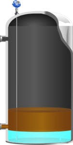
Figure 1. Any level-measuring technology must detect and measure an oil/water interface in the tank.
When the separation process is incomplete, oil and water go where they shouldn’t. A layer of oil accumulates in the water tank, introducing safety risks and product loss as it is hauled away for disposal. Conversely, water can accumulate in the oil tank, which degrades the quality of the product. Two level technologies (see Figure 1) can measure the oil-water interface together with the surface level: magnetostrictive and guided-wave radar (GWR). Both can provide the necessary precision to satisfy 18.2 and are unaffected by cold, rain or any other distractions to a human operator.
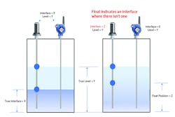
Magnetostrictive level measurement instruments use floats that move on a rod extending down to the bottom of the tank. The bottom float is weighted so it sinks in oil but floats in water, whereas the upper float always remains at the top of the oil. The sensing mechanism can determine the position of both floats. This approach works well if there is no gooey buildup on the rod so the floats can move freely. When there is a distinct interface, this technology also can provide a reliable indication for both overall level and interface level. However, when an emulsion forms and causes an ambiguous oil and water separation, magnetostrictive technologies will incorrectly report a distinct interface. The interface float will always come to rest somewhere, regardless whether there is good product separation or not. This provides a false sense of certainty that the true location of the interface is known.
Solids and gooey tar-like materials are common with crude oil, and they can coat the walls of the tank and the probe of a level instrument. With a magnetostrictive instrument, the float (or both floats) can become partially or completely glued in place, so they do not move freely or do not move at all in worst cases. This has a major detrimental effect on the accuracy of the measurement, and an operator will not be able to tell what’s happening beyond readings freezing. The more insidious problem is a loss of accuracy if the float can move partially but drags, reducing repeatability. This is not as easy to recognize from the readings.
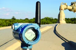
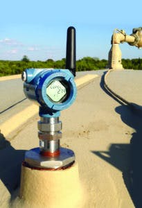
Figure 2. A GWR transmitter, such as the Rosemount 3308 from Emerson Automation Solutions, works well in oil storage tank applications.
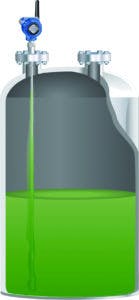
A GWR level instrument has a transmitter (see Figure 2) mounted on top of the tank, with a probe hanging down to the bottom. The probe serves as a wave guide to carry the radar pulse down to the surface of the liquid. It can measure the distance far more accurately and with better repeatability than a human taking manual tape readings. When water sits below the oil, some of the microwaves pass through the oil so that an additional reflection is made from the interface between the oil and water. There are no moving parts, so the instrument is tolerant of buildup on the probe.
In general, it is unnecessary to clean a GWR probe. However, the device does have the capability to alert an operator if buildup is affecting the reliability of the measurement. The nature of the echo created by a dirty probe (see Figure 3) is different than a clean probe. The difference can be quantified as a variable designated signal quality. Should the signal quality ever drop below a critical level, operators can be warned of the problem so they can take appropriate action. When the alert is triggered, online help will give the operator instructions on how to remedy the problem.
As mentioned earlier, the key operational differences between magnetostrictive and GWR hinge on how they deal with the oil-water interface. If the two layers are distinct, either can provide a clear measurement. However, where the separation is indistinct, the lower magnetostrictive float will still come to rest where the density change is sufficient to cause buoyancy, so it will indicate an interface whether one exists or not. When a GWR transmitter is used, if no distinct interface is present, it will not indicate one.
Figure 3. When the echo loses its clarity, material buildup on the probe is usually the problem.
While the magnetostrictive device drives an incorrect reading under this condition, the GWR provides useful information. The conditions leading to a loss of interface can result from pushing too much oil through the separator without sufficient residence time. This can drive excessive water carryover to the oil storage tank, making it effectively a secondary separator. This inefficiency can be prevented by also using a GWR transmitter in the separator and using this valuable feedback from the GWR transmitter to identify a loss of interface. Should this occur, the flow through the separator can be throttled back until the interface is restored.
Other elements of custody transfer
Using automated level measurement takes care of the beginning and ending level readings, but referring back to the list of tasks addressed earlier, there are other necessary measurements that may now be accomplished without climbing the tank, and the following are some examples.
Temperature measurements still need to be taken, but these can be done in the pipe between the tank and truck, rather than in the tank. In fact, the ability to take a continuous temperature reading during the product transfer allows for the temperature to be averaged over the entire transfer. Using this method provides a temperature value that is much more representative of the overall product transferred and therefore contributes to better transfer accuracy.
Samples still need to go through the grind-out process and then a check with a hydrometer. These samples can be captured easily and safely using a small valve, which can be opened manually during the transfer process.
The sample collection valve and temperature sensor can be built into a short pipe section of the same diameter as the transfer pipe. Usually these lines use cam-lock fittings, so it is a simple matter to create a short section that can be inserted wherever practical.
Few tanks, if any, are built with the kind of precision equaling the capability of a level transmitter. In other words, some sections of the wall are probably a little flat in spots, so a tank will vary at different levels. Consequently, tank strapping tables can improve the accuracy of a transferred volume determination since the change in level is used to determine volume.
For example, in a given tank, the amount of oil necessary to cause a 24-inch change in level near the top of the tank can be a measurably different volume than the same level change near the bottom due to tank bulging and irregularities in the tank geometry. When tanks are commissioned for this application, great care is taken to create a lookup table to correlate a level measurement with the actual volume corresponding to that level. These tables are derived using a precise flowmeter combined with an accurate level measurement device.
Is using a level transmitter accurate enough for custody transfer?
When API 18.2 was drafted, the objective was to facilitate product transfer with the same or better accuracy than using the manual methods defined in API 18.1. Remember that API 18.1 required three consecutive manual readings to be in agreement within 0.25 inches. Fortunately, the committee recognized the industry has already deployed thousands of level transmitters in their fields with accuracies of ±0.125 inches, thus providing for much better accuracy than manual methods.
Figure 4. Recognizing when the interface is indistinct can help an operator avoid sending out mixed product streams containing a high percentage of water in crude oil.
These devices are specified by their manufacturers to be highly accurate, but is it possible to prove accuracy in practice and maintain accuracy over time?
GWR technology works by measuring the time of flight for a pulse to travel from the electronics down the probe and back again. As such, the components affecting the accuracy of this time travel are contained within the electronics in the head and not the probe. This makes it possible to routinely remove the head and test it using a NIST-traceable calibration box. Such a device simulates distance electrically using coaxial cables of known lengths. Up to five different lengths can be used to verify the transmitter over a broad operating range, and a report can be generated to provide a permanent record of device compliance.
Working together, these elements can produce a higher level of accuracy while avoiding potentially lethal safety concerns. API 18.2 shows how users can put these techniques to work to produce the desired results in a safe and repeatable manner with minimal requirements for on-site labor.
Tom Wienke is the level business development director at Emerson Automation Solutions. He has a bachelor’s degree in mechanical engineering from the University of Minnesota. Wienke has been employed with Emerson for the past 27 years and has experience with operations, customer support, product management and marketing. Based in Minneapolis, he currently leads an eight-member team supporting Emerson’s level business across North America.
