One of the characteristics of raw crude oil is its salt (primarily sodium chloride) content, which varies according to naturally occurring ground deposits and extraction methods. While the solubility of salt in oil is much lower than in water, enough can be carried into the refining process to cause corrosion problems for equipment. Salt can also contain metals that may poison catalysts used downstream, so it must be removed. Fortunately, it dissolves far more readily in water, so if water is mixed with the oil, the salt washes out.
While this sounds like a simple process, doing it on the scale necessary to feed a refinery poses challenges. To handle the volume, a desalter is typically its own subunit at the beginning of the refining process. While actual equipment configurations vary, most designs inject water into the oil stream using a mixing valve. Since oil and water do not naturally mix, an emulsifier is added to help disperse the water and maximize contact to make the salt transfer as complete as possible.
Eventually the injected water and any water that came in with the crude (which is now brine since the salt was taken from the oil), will separate from the oil. Oil going into the next processing stage needs to have salt content below one pound per thousand barrels crude feed to avoid fouling and corrosion of downstream equipment.
However, keeping up with the flows required for the process using a gravity separation method alone would call for an extremely large tank to provide the necessary residence time to ensure full separation. Since refineries need to maximize throughput, they use a desalter rather than rely on gravity to ensure full salt and water removal.
Driving volume with effective desalter separation
The oil, water and emulsifier mixture is injected through a mixing valve into a large horizontal vessel, typically around 15,000 to 20,000 gallons. The liquid in the tank separates into oil on top and water (brine) on the bottom, with an intermediate emulsion layer. Depending on the mix proportion, the water is typically about 20 to 30 percent of the volume in the tank.
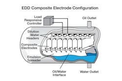
To maximize water removal, the desalting tank is equipped with an electrostatic grid immersed in the upper oil section (see Figure 1). When charged, this causes any small water droplets still in the oil to coalesce so they sink more quickly down into the bottom layer. Given oil’s poor electrical conductivity, these grids can be run around 10 kilovolts or higher, which makes for fast and effective separation.
Washed and dried oil is drawn out of the top, and water, salt and emulsifiers go out the bottom. The emulsion layer remains static in the middle. When the system works correctly, the oil leaving the unit is effectively free of salt and water, with these contaminants reduced to the point where they will not cause processing problems. Many refineries have gone a step further by using a two-stage process in which treated crude from the first desalter goes to a second desalter for additional salt removal. With one-stage desalting, about 95 percent of the entering salt can be removed, while the efficiency increases to 99 percent for typical two-stage desalting.
Maintaining control for efficiency
While in operation, the desalting tank is completely filled, but an interesting level-measuring challenge is present, since three layers within the tank need to be monitored. The unit works best when the highest amount of water can be injected into the oil stream, but practical limitations require careful control.
For maximum coalescing efficiency, the oil level in the tank should just cover the electrostatic grid. While oil is effectively an electrical insulator, salt-laden water is highly conductive, so if the water level in the tank is high enough to reach the grid, it can short the system or at least cause excessive power draw.
Consequently, operators must know exactly where the top of the middle emulsion layer is. They can control its position by regulating the mixing valve, as well as the flow of oil and brine leaving the tank. The setting of the mixing valve determines the proportion of water, oil and emulsifier entering the tank. The emulsifier must be purchased and goes out with the waste stream, so minimizing its use reduces cost, but minimum separation levels must be maintained.
The challenge is measuring the height of the interface layers. One crude but effective method is installing "bleed taps," a series of pipe penetrations through the side of the tank at various levels, each closed off with a valve. To locate the interface, an operator simply opens one valve after another until the desired product comes out. This is environmentally messy and dangerous since these units can operate at temperatures up to 300ºF and pressures up to 190 psi. It is also impractical to use such a manual method for control when a high emulsion layer level can shut down the plant.
The elusive continuous interface measurement
The concept of measuring the position of an oil/water interface is nothing new. One of the traditional methods is a magnetostrictive instrument with a float designed to sink in oil but float in water. Capacitive level instruments can do something similar. Unfortunately, the special conditions in this application make these difficult to use.
Interface measurement is challenging in this application because the oil and water layers have varying properties:
- Their densities change as the temperatures change.
- The density of water changes as the amount of salt or other contaminants changes.
- Oil density and viscosity can change with different crude feed types.
- The emulsion layer is an indistinct interface between the fluids and can be difficult to read.
- The crude can contain sticky components that coat surfaces or cause mechanical parts to stick.
Magnetostrictive or capacitive technologies or displacers have traditionally been used to measure interfaces. But changing component densities can result in unpredictable measurements for all these technologies. Moreover, the emulsion and oil tars can get gooey, interfering with the free movement of the float, coating capacitive probes and throwing off measuring accuracy. The desalter unit must be shut down to remove either type of sensor for cleaning or recalibration, which is another major disadvantage. But there is a better way.
Measuring with radar
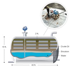
One thing working in the operator’s favor is the difference in dielectric characteristics of all three layers. Since guided wave radar (GWR) level instruments operate by finding those differences, this application takes full advantage of that capability (see Figure 2).
A level transmitter can generally identify the top of the emulsion layer with a single probe and can often accurately measure the position of all three layers, depending on their thickness and dielectric characteristics. Readings can be taken continuously and are unaffected by the electrostatic fields during operation as long as the grids are properly grounded. This product family has signal processing capabilities able to boost the unit’s ability to read through fluids of low dielectric strength such as oil. It is also immune to density changes, has no moving parts that could stick because of coating, and has diagnostics capabilities to alert users before any coating would affect the measurement.
A slotted stilling well for the GWR transmitter can help with measurement of the interface in some applications, but it is recommended that the stilling well be at least 4 inches in diameter and have as many slots as possible since the slots affect the resolution of the layers inside the stilling well compared to the rest of the tank. Using data from the tap samples, it is possible to check that the measurement of the transmitter gives an accurate picture of the top of the emulsion layer and any layers below.
Since the tank is usually hot, consideration should be made so that the transmitter does not exceed the recommended temperature for its electronics. In some cases, a remote connection may be needed to move the transmitter further from the tank.
Improving operational results
Efficient operation of a desalter unit minimizes corrosion and fouling in downstream process units and prevents poisoning downstream catalysts caused by residual salt. Simultaneously reducing water content to below 0.5 percent also helps avoid overpressure incidents in the crude distillation column.
With reliable interface level control, a desalter can operate more efficiently and reduce water and salt carryover to the crude unit while avoiding a unit shutdown due to shorting the grid. Effective separation of the oil improves its quality and reduces oil contamination to the downstream water treatment plant, reducing the need for maintenance and associated downtime.
Lydia Miller is senior marketing engineer, level, for Rosemount, part of Emerson Automation Solutions. She holds a bachelor’s degree in mechanical engineering.


