Fluid power systems are the lifeblood of the mechanical world. Flow readings provide a means of assessing the performance of hydraulic and pneumatic circuits within these systems and aid troubleshooting when malfunctions occur. Leaks are often the result of poor system design, substandard component quality, improper installation and abuse.
The following explains why variable area flowmeters are a proven and practical solution for use in fluid power applications. These cost-effective devices provide a clear indication of hydraulic line health during operation — without the dangers of coming in close contact with machinery. They allow for improved flow visibility to pinpoint hydraulic fluid leaks so users and the environment stay safe.
Background
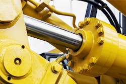
Fluid power involves the use of fluids under pressure to generate and transmit power for the control of force, torque, position and motion in various types of equipment and machinery. The difference between hydraulics and pneumatics lies in the medium that is used to transmit power. Hydraulics employs relatively incompressible liquid media such as mineral oil, ethylene glycol, water or high-temperature fire-resistant fluids to make power transmission possible (see Figure 1). Pneumatics use easily compressible gas such as air or pure gas.
Due to the impressive power it can achieve, hydraulics is commonly used in commercial and industrial applications that involve lifting, pressing and operating machinery. Small leaks in most hydraulic equipment are difficult to avoid, and in some cases, they are acceptable if easily controlled. However, if left undetected, smaller leaks can become larger, causing machinery failure.
Many different costs are associated with the downtime of a piece of equipment. The more obvious costs are directly related to the problem, including the cost of materials and parts, the labor of the technician who fixes the problem and the cost of the facility or location where the equipment is being repaired, among others. In addition, there are costs that are not so obvious, such as opportunity cost, where the downtime of the machine will affect other jobs or production processes that will be delayed due to the current incident.
Critical operating challenges
Fluid power systems are susceptible to a wide range of operational hazards. They are equipped with filters and other measures to preserve the cleanliness of the working fluid. However, any dirt in the system can cause wear of seals or obstruction of control valves, resulting in erratic operation or failure.
It is important to control both pressure and flow in hydraulic circuits to ensure safe and accurate movement of loads in fluid power applications. Maintaining a proper load requires the correct fluid pressure. If the pressure becomes too high, the fluid will try to escape any way possible.
Flow can exit a hydraulic circuit through external or internal leakage. External leakage, such as a burst hose, is usually obvious and therefore easy to find. Internal leakage can occur in the pump, valves or actuators, and it is more difficult to isolate.
A reduction in machine performance is often the first indication of a problem with a hydraulic system. This usually manifests itself in longer cycle times or slow operation. Because flow determines hydraulic actuator speed, a loss of speed may be directly related to a loss of flow.
There are generally two different paths to take when trying to get a fluid power system up and running again. Users can buy and install the new parts or attempt to repair the equipment. Either way, an experienced technician with the appropriate tools is needed to find, diagnose and make the decisions for repair and maintenance of a system.
Need for flow measurement
Monitoring the condition of fluid power systems and accurately diagnosing the sources of problems can prevent unexpected failures and reduce unplanned maintenance and downtime. With today’s emphasis on making hydraulic equipment more productive, it is important to catch minor problems before they become major headaches.
Modern fluid power systems rely on a combination of pumps, cylinders, hoses, actuators and fluid to operate. Flowmeters are an essential tool to measure the flow of hydraulic fluid to monitor pump performance and ensure unobstructed fluid movement.
Unfortunately, many companies that employ hydraulic equipment use flowmeters after the fact — when an event has already occurred — to locate and/or diagnose failures.
Experience has shown that having a permanently installed flowmeter within a hydraulic or pneumatic circuit can allow for real-time monitoring of asset health and provide valuable insight into process conditions. Ensuring that end-of-line tools and equipment are receiving proper flow rates can prevent premature failure of equipment, reduce fuel and energy costs associated with underperforming systems, minimize costly downtime and be a valuable metric for a preventive maintenance strategy, which is critical for extending component and machine life.
Choosing the right solution
Many types of flow devices are available for measuring liquids and gases, so identifying which flowmeter is appropriate for a particular measurement environment requires knowing the difference between them.
When searching for the right flowmeter, the following questions can help:
- What is the fluid?
- What are the fluid properties?
- What are the operating conditions?
- Why is flow being measured?
- What is the flow range?
- How accurate does the flow measurement need to be?
- What effect might the flowmeter have on the fluid and vice versa?
- Is power available?
- Is an output required?
- What is the budget?
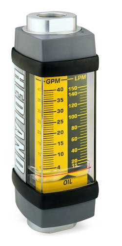
Variable area flowmeters are often the first choice for volumetric flow rate measurement in fluid power applications due to their simple and reliable metering technique. Traditional variable area meters consist of a tapered tube (glass or metal) and a float, which could also be described as a shaped weight. As the flow increases, the float rises in the tapered tube until reaching a point where the upward force exerted by the flow and downward force of gravity are in balance. As the float settles to a stable position, a reading can be taken — typically by using the top of the float as a point of reference against an internally mounted flow scale (see Figure 2).
Figure 2. Variable area flowmeters are often the first choice for fluid power applications due to their simple and reliable flow-metering technique.
Compared with turbine flow meters, which are normally selected for high-accuracy applications such as hydraulic fluid characteristic measurement on test stands and feedback for a hydraulic system control, variable area flowmeters meet a diverse range of fluid power requirements. The main reasons to select this metering technology include:
No need for external power: Variable area meters are mechanical devices, which do not require power to provide flow measurement. This allows the meters to be installed in hazardous and remote areas where it would be expensive to supply power.
Ease of viewing the process: With variable area meters, end users not only get a flow measurement reading, but also get a look into their process. If the process looks dirty or cloudy, it could mean filters need to be changed. The visual reading can also indicate if the process is the correct color or if there are bubbles in the liquid, for example.
Low overall cost: Both variable area meter price and function contribute to savings on the job. The meters can be installed with other flow measurement technologies and used to complement each other at an economical price.
Simple installation and maintenance: Variable area devices are quickly installed by connecting the process line to the inlet and the outlet of the meter.
Low pressure drop: Most variable area meters have only a few inches of water column pressure drop. This allows them to be installed in many places in the process. Small pressure drop also means smaller pumps.
Repeatability: Given the same process conditions, a variable area meter will accurately repeat the flow measurement day after day.
Latest design enhancements
Industrial organizations continue to choose variable area flowmeters for fluid power applications due to their proven performance advantages and low cost of ownership. These meters provide a direct visual flow indication to keep systems running safely.
Flowmeter manufacturers have enhanced the tried-and-true variable area design to keep pace with changing customer requirements. For example, one major disadvantage to using gravity as the balancing force on a variable area device is that the meter must be installed in a vertical position to work properly. The latest variable area design replaces gravity with a "calibrated spring," which opposes the flow in the forward direction. This approach provides a number of distinct advantages over a gravity-based balancing force, including:
- Variable area meters can be mounted in any position without affecting accuracy. An optional inverted flow scale is available for inverted flows.
- The calibrated spring decreases viscosity sensitivity, providing greater versatility than a standard variable area meter using gravity as the balancing force.
- The calibrated spring design is inherently less sensitive to shock and vibration when compared to other variable area flowmeters.
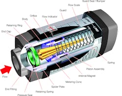
With the spring-loaded variable area configuration, a precision-machined and sharp-edged orifice located within the piston assembly forms an annular opening with a contoured metering cone. The piston assembly carries a cylindrical ceramic magnet, which is magnetically coupled to an external flow indicator moving in direct response to movement of the piston. A calibrated spring opposes flow in the forward direction. This spring decreases viscosity sensitivity and allows the flowmeter to be used in any position, including an inverted bidirectional flow capability. If required, a reverse flow bypass option can be specified (see Figure 3).
The advanced variable area design does not require special plumbing or accessories to stabilize turbulent flow. Flowmeters can be installed immediately adjacent to 90-degree elbows or other components to provide the greatest system flexibility, while saving installation time and money. This design is also inherently less sensitive to shock and vibration than traditional variable area meters. The use of magnetic coupling greatly reduces the chance of decoupling the flow indicator under high flow and pressure transients. In addition, it eliminates the need for mechanical linkages that can wear, loosen and leak over the functional life of the meter.
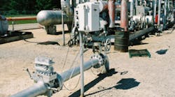
In applications where a permanently installed flow device is not feasible, the use of variable area meters, flow switches and test kits with a pressure gauge provides a quick visual flow indication on a linear scale to confirm that flow circuits and on-machinery hydraulic or pneumatic systems are operating properly. Furthermore, microprocessor-based flow transmitters can be used to present flow rate and totals on a digital display and have the ability to transmit data to remote locations.
Figure 3. The modern spring-loaded variable area flowmeter design decreases viscosity sensitivity and allows the meter to be used in any position, including an inverted bidirectional flow capability.
Conclusion
Flowmeters are essential for accurately monitoring process conditions, diagnosing system errors and ensuring pump performance in fluid power systems. Today’s variable area flowmeters are ideal for determining equipment health and detecting leakage or other problems in hydraulic circuits. They are versatile and cost-effective and offer reliable, low-maintenance performance.
Ryan Kalinoski is a product specialist at Badger Meter. He may be reached at rka[email protected]. For more information, visit www.badgermeter.com.
