Storage tanks are used to hold crude oil for a period of time to stabilize oil flow between production wells and pipelines. According to the Environmental Protection Agency (EPA), the United States has approximately 500,000 crude oil storage tanks and, in 2011, Standard 40 CFR, Part 60, Subpart OOOO was indoctrinated to begin the monitoring and recovery of vapors in such tanks. Condensate liquids that disconnect during the natural gas separation process are also stored in these tanks.
During storage of crude oil and condensate, light hydrocarbons tend to vaporize and accumulate between the roof of the storage tank and top of the liquid. Over time, with fluctuations in level and temperature, these tanks can produce large amounts of gas vapor that must be either vented to the atmosphere, flared or collected. As the price of oil rises, many oil producers realize they may derive financial savings by installing vapor recovery units that collect the vapor and, then, process it. These units also help to reduce the amount of harmful vapor being discharged into the environment as collected vapor can be converted into a liquid state and pumped back into the storage tank or used as a fuel for other applications.
READ ALSO: How to Calculate Readings for Compound Pressure Transducers
Vapor Recovery Unit (VRU)
A VRU is comprised of a suction scrubber, compressor and automated control unit. These components, along with oil coolers, fuel-gas and water knockout tanks, are mounted on a skid that is shipped to the tank or tank farm and positioned for use. The compressor can be a screw, scroll, reciprocating, or piston configuration and is normally belt-driven by an EPA-approved engine.
A precision pressure sensor measures the pressure of the tank in the range from -2.5 to 2.5 PSI and provides the electrical output as part of the closed-loop feedback system. As the pressure rises, the compressor turns on and starts the compression cycle.
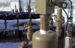
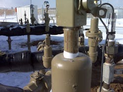
Figure 1 shows a VRU skid with a precision pressure sensor (on the top-right) as part of closed-loop feedback circuit that maintains the system pressure.
Figure 1 Precision pressure sensor (on the top-right) as part of closed-loop feeback circuit
Pressure Sensing
Pressure sensing plays a vital part in the control and smooth operation of the VRU. Since the pressure sensor is mounted on the outside of the tank, it is important that the device operate reliably in fluctuating temperatures down to -40 C (-40 F) and up to 60 C (135 F), while providing precise and consistently accurate readings over time.
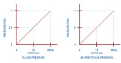
While most VRU systems employ unidirectional pressure sensing that gauge as 0-1, 0-2 or 0-2.5 PSI, some require readings in the negative range such as +/- 1 PSI, +/- 2 PSI and so on (see Graph 1). Here, it is important that the output is linear from 0 to positive pressure as well as 0 to negative pressure.
As shown in Graph 1, based on what type of pressure readings are required to maintain a VRU system, a gauge pressure transmitter that offers positive readings or a bi-directional pressure sensor that provides readings in the negative range may be used to monitor tank pressure.
Graph 1. Some VRUs require readings in the negative pressure range.
Since measurements are small and require gauge measurements with respect to the atmosphere, pressure sensors need to vent to the atmosphere. It is important that venting be engineered correctly so no moisture or water ingress enters the pressure sensors that can limit its life or accuracy.
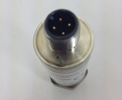
Venting can be accomplished closer to the sensor where connectors are used or, ideally, via a cable with vent tube that is terminated in a weatherproof enclosure. While venting through connectors is cheaper, the vent filter can clog in humid and outdoor applications involving dust, ice and water, resulting in huge errors that can cause the system to become unstable.
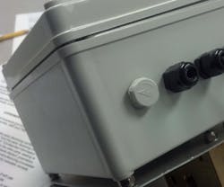
Figure 2 shows local venting conducted near the connector terminals. Figure 3 shows venting conducted via a vented plug mounted in an enclosure for outdoor use where the sensors are terminated with cables with integral vent tubing.
Figure 2. Local venting near connector terminals
Figure 3. Venting conducted via a vented plug mounted in an enclosure
Pressure Sensor Approvals
The location of the sensor in the hazardous location will determine the approval required for the sensor. Most VRU systems are located in the Division 2 area, requiring a sensor with Class I Division 2 rating. The sensor itself is typically located outside an atmosphere where hazardous conditions exist. The electrical connection can require protection of the cable by use of a conduit or connector that is sealed with a lockout device. The ultimate goal of this configuration is to prevent connecting or disconnecting the sensor while the device is powered or cutting the cable to cause an ignition source.
Other possible pressure sensor selections can include an intrinsically safe unit, where the protection of the transducer is maintained through a Zener barrier or an explosion-proof transducer that is protected through a factory-sealed conduit connection with wire leads. Selection of these pressure sensors depends on the environment where the VRU system is located.
Reference
1. “Lessons Learned from Natural Gas STAR Partners: Installing Vapor Recovery Units on Storage Tanks,” www.epa.gov/gasstar/documents/ll_final_vap.pdf.
www.astsensors.com
