For any magnetic flowmeter (magmeter) system to function properly it must have three connections (including a ground) to the process liquid passed from the magmeter flowtube onto the magmeter flow transmitter. About 80 percent of the time, problems with the flow measurement readings provided by a magmeter can be traced directly to improper solution ground connections.
The SG connection is actually the reference point of the measurement, and it is required for a magmeter to consistently achieve a stable zero flow measurement reading, as well as to provide accurate measurements during flow. Without this reference SG connection, there can be no confidence in the flowrate measurement.
READ ALSO: Magmeter Basics—A primer on selecting & applying electromagnetic flowmeters
Two main causes are responsible for the majority of solution ground connection problems. First, the SG connection from the process to the magmeter flowtube’s body/case is missing. Secondly, the SG connection fails to pass properly from the magmeter flowtube’s body/case onto the magnetic flow transmitter’s SG terminal.
Magmeter Grounding Rings vs. Grounding Electrodes
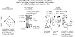
In order to determine when to use grounding rings or grounding electrodes, the first thing that must be understood is their primary function, and if they are even required. The primary function of grounding rings or grounding electrodes is to provide the required SG connection when unlined metal process pipe is not available. Grounding rings are metal rings that make contact with the process liquid. These rings are installed between the process pipe and the magmeter flowtube. These metal rings must then be attached to the flowtube’s body/case or flange in order to pass on this SG connection—usually by some wiring or bolting method, depending on the style of grounding ring used. Examples with detailed illustrations are shown in this article. In addition to providing the required Solution Ground, a grounding ring on the upstream side of the magmeter flowtube also provides a fair degree of liner protection to the leading edge of the flowtube’s liner when used in moderately abrasive applications.
For many of the more hazardous process liquid applications, magnetic flowmeter systems are often the preferred technology simply because they are available with numerous liner and exotic electrode material choices, thus providing compatibility with many hazardous chemicals. If grounding rings or grounding electrodes are required, they should be made from the same material as the measuring electrode based on chemical compatibility with the process liquid.
In hazardous process liquid applications, the adjacent process piping is usually nonmetallic or lined. Because grounding rings made from exotic materials are rather expensive, grounding electrodes can offer substantial cost savings over grounding rings and provide easier installation with fewer leak-points.
Contact the supplier to determine which flowtube models are available with grounding rings and/or grounding electrodes.
Does the Magmeter Need 1 or 2 Grounding Rings?
For decades, two grounding rings were always the recommendation when required for magmeters. When using older style legacy magnetic flow transmitters, this is still true. However, with current intelligent microprocessor-based magnetic flow transmitters, two grounding rings are no longer necessary, as the same level of zero stability and accuracy can be provided with just one grounding ring. This not only reduces the overall cost of materials, but also makes installation easier.
When using one grounding ring, it should be placed on the upstream side of the magmeter flowtube. In addition to providing the required solution ground, placing this grounding ring on the upstream side of the flowtube also provides a fair degree of liner protection to the leading edge of the flowtube’s liner when used in moderately abrasive applications.
How Magmeter Flowtube Installation Affects the Solution Ground
Proper flowtube installation is critical for correct SG in magmeters. In the case of metal process piping, a properly installed flowtube means that no additional solution grounding rings or electrodes are required. For nonmetallic pipe or liner configurations, a solution ground method is required, and careful attention must be paid to grounding ring or electrode connections and placement. The following provides some tips for proper SG connections to the magnetic flow transmitter.
SG Connection with Metal Process Pipe
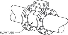
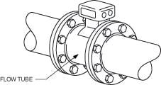
Flanged-style flowtubes: The most common method of passing the SG connection from the process itself onto the magnetic flowtube’s body/case is through flanged, unlined, metal process pipe bolted to a flanged magnetic flowtube (Figure 1).
When the metal flanges on each side of the magnetic flowtube are bolted to the magnetic flowtube’s metal flanges, the SG connection is made. It passes onto the magnetic flowtube’s body/case, and eventually to the magnetic flow transmitter. In this metal-to-metal installation scenario, neither grounding rings nor grounding electrodes are required.
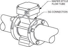
Wafer-style flowtubes: Wafer style flowtubes have no flanges of their own. Therefore, when a wafer-style magnetic flowtube is mounted between flanged, unlined, metal process piping, the proper method of passing the SG onto the flowtube is by attaching supplied SG wires that ship with the flowtube. Be sure to connect these wires to the metal process pipe flanges on each side of the wafer flowtube (Figure 2).
In this installation scenario, grounding rings are not required. Note that grounding electrodes are not available on wafer-style magnetic flowtubes; the supplied wires are to be used.
SG Connections with Nonmetallic/ Plastic/PVC/Lined Process Pipe
Flanged-style flowtubes: When flanged-style flowtubes are mounted between nonmetallic, plastic, PVC or lined process piping, the SG must be passed to the flowtube’s body/case through some path other than the process piping flange bolts. In such installation scenarios, either grounding rings or grounding electrodes are required (Figure 3).
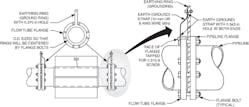
For grounding-ring applications, if traditional orifice plate-style, or Type C, grounding rings are used, the grounding rings must be attached to the flowtube’s body/case using grounding straps. These straps are attached to the flowtube’s flanges, or to grounding wires attached to a lug located on its remote junction box or top-mounted transmitter interface plate. Type E grounding rings utilize customer-supplied bolts, rather than grounding wires or grounding straps.
For process pipe that is lined with a nonmetallic material, the ring configuration is slightly different. Figure 4 shows the application of Type E and Type C grounding rings in lined process pipe configurations.
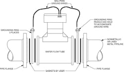
Wafer-style flowtubes: When wafer-style flowtubes are mounted between nonmetallic, plastic, PVC or lined process piping, grounding rings are required. The SG must be passed on to the flowtube’s body/case by connecting the attached, supplied SG connection wires to the grounding rings (Figure 5.)
As with flanged flowtubes, if traditional orifice plate-style, or Type C, grounding rings are used, the grounding rings must be attached to the wafer-style flowtube’s body/case using grounding straps or wires. The grounding wires are attached to a lug located on its remote junction box or top-mounted transmitter interface plate. Type E grounding rings utilize customer-supplied bolts rather then grounding wires or grounding straps.
It is important to remember the purpose of the solution ground connection is to serve as a reference point of the flow measurement. This lets the magnetic flowmeter read a stable zero flow and achieve accurate measurement in flow conditions. The placement and type of SG and connection devices is critical in meeting this goal. The method used varies with the range of flowmeter body types, process pipe construction and liner materials. When all of these factors are considered, and the proper SG configuration is employed, results will meet performance and consistency expectations. Without a properly installed solution grounding method, confidence in the flowrate measurement will be diminished.
Clifford Read is a technical support engineer in the Field Devices Technical Assistance Center for Invensys Process Systems. He has been involved in the process control industry for 24 years, and his primary focus for the past eight years has been on flow product application consulting and troubleshooting. Additional fields of expertise include instrument configuration software/hardware marketing support, testing, as well as client-side troubleshooting support. Mr. Read can be reached at 508 549-4540.
