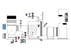
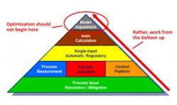
The purpose of boiler control is to achieve safe operation, reliability and optimized performance with respect to load-change response, fuel cost and emissions. While operators may be tempted to think that periodic adjustment of the fuel-to-air curves or control loop constants will lead to optimum performance, the reality is that the quality of measurement and actuation field devices is the foundation for building optimal control (see Figure 1).
Figure 1. The quality of measurement and actuation field devices is the foundation for building optimal control.
Often when operating issues occur, a work order is issued to "tune up the boiler." This may appear to help for a while, but loop tuning and curve adjustment will not overcome field device issues at the root of many boiler operation difficulties. To truly resolve reliability issues and achieve a step change in boiler performance, operators often must work with the instruments and actuators.
In most control applications, repeatability of measurement is more important than absolute accuracy. Accuracy can be adjusted for software, but erratic readings cannot. The only way to compensate for lack of repeatability is to build excess "cushion" into the control, which compromises reliability, response and business results.
Even the most basic boiler processes, such as the single burner package boiler (see Figure 2), require different types of process instrumentation. If any one of these devices does not perform adequately, it is likely that unit performance will suffer. Unfortunately, making some of these measurements reliably can be challenging. This article concentrates on four measurements key to boiler control performance:
- Drum level
- Fuel flow
- Air flow
- Flue gas oxygen
Drum level
Drum level is critical for safety and reliability. Inaccurate drum level control can result in safety issues and equipment damage. High levels can cause water carryover that lowers heat transfer efficiency and possibly damages downstream equipment such as steam turbines. Low levels expose tubes to excessive heat, resulting in tube damage and unplanned shutdown.
Drum level measurement is not as simple as it might appear. Typical challenges include the need for high-pressure and high-temperature equipment, the fact that density and dielectric (DC) of water and steam vary as pressure and temperature change, and that the control ranges across a small span.
Another issue is the shrink and swell phenomenon. As steam demand decreases, drum pressure increases, which compresses entrained steam bubbles and can cause the drum level to appear to decrease even though it actually increases. Conversely, as steam demand increases, drum pressure decreases, and the gas bubbles expand, often causing the drum level to appear to increase.
To help compensate for shrink and swell, boiler control engineers employ three-element control strategies that simultaneously look at steam flow, the rate feedwater is flowing to the steam drum and the water level in the steam drum. In addition, compensation for pressure and temperature must be made either at the level instrument or in the computer control system.
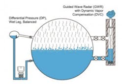
Figure 3. Drum level measurement redundancy is best achieved by using different instruments such as both DP and GWR.
Redundant drum level measurements are recommended for safety and reliability, and because a steam drum can be uneven because of irregular heating over time, redundantly measuring on the front and back is often preferred. Another best practice is to use different measurement technologies for measurement redundancy. Figure 3 depicts one way to obtain measurement redundancy by combining differential pressure (DP) and guided wave radar (GWR) level technologies.
GWR can be especially advantageous in obtaining a reliable drum measurement for cases in which the level is continuously swinging. The separate measurement chamber used with GWR can dampen the effects of load swings and shrink/swell to a degree. GWR measures the time of flight of an electromagnetic pulse. It is independent of density, but steam DC can cause up to 20 percent error and varies with pressure changes. For this reason, compensation must be made for DC when using this level technology.
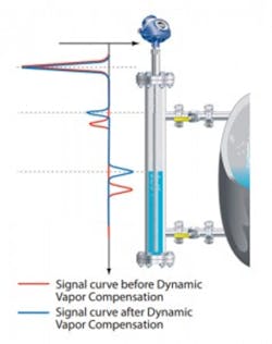
Figure 4. DVC works by inserting a fixed reflective object in the path of the radar waves, well above any expected liquid level. The GWR compares the measured distance to the reflector with its known distance to create a compensation value that it then applies to all readings.
Compensation can be accomplished in the computer controls, but obtaining a DC value for what the GWR sees is often difficult. A more direct approach is to work with a GWR device that carries out this compensation internally. Called Dynamic Vapor Compensation (DVC), it works by inserting a fixed reflective object in the path of the radar waves, well above any expected liquid level (see Figure 4). The GWR compares the measured distance to the reflector with its known distance to create a compensation value that it applies to all readings. Because it determines this correction value continuously, it corrects measurement errors under all conditions and reduces the error rate to less than 2 percent.
Fuel flow considerations
The approach to optimizing combustion is fundamentally a drive toward achieving mass balance between fuel and oxygen, so fuel measurements should be of the mass flow type. An important question to answer when selecting instruments for fuel flow is simply, what varies?
If process variables are all nearly constant, volumetric flow measurement is the least expensive choice, and it can be a good one. However, changes in the rate of fuel flow, temperature, pressure or heating value require a meter that is able to address these changes or one that is relatively insensitive to them. Each variation may induce errors in volumetric meters used on gaseous fuels.
Pressure changes will be present in nearly every fuel measurement because of pipe-friction-induced pressure loss between the regulator and the meter, regulator droop and barometric variation. When fuel pressure and temperature changes are the primary cause of variation, external compensation can be added to the flow meter to improve its accuracy. A better option is to utilize multivariable mass transmitters that compensate for changing pressure, temperature or flow rate at the instrument.
Some boilers, however, are fueled with process gas, waste gas, or whatever may be a least-cost fuel at a point in time. Since the heating value of such fuels can vary over a wide range, a direct mass Coriolis flow measurement is typically best in this situation. All types of mass flow meters improve turndown, which helps when the boiler experiences wide load swings. In addition, any changes in feedwater temperature will require corresponding changes in firing rate.
Flow measurement generally involves weighing trade-offs between a number of factors. Other issues that commonly influence meter selection and installation method include meter pressure loss (because fuel is often delivered to the boiler at low pressure), available straight run, and of course, lifecycle economic factors.
Knowing the fuel mass rate means knowing the rate at which energy (Btu/calories) is being delivered to the burners, which in turn determines the amount of air required. This makes it easier to control combustion, monitor boiler efficiency and monitor plant energy use, even with compressible fuel. Further, it makes environmental reporting easier.
Air flow considerations
Boiler air flow measurement is often a challenge because of the physical arrangement of fans and ductwork. Ducts often have odd geometries and many turns, with dampers, expansion joints, internal restrictions, conditioning vanes and service access doors. Often internal restrictions are not even documented. For traditional air flow instruments, specifications typically call for extended straight upstream and downstream sections of duct with no bends, expanders, dampers or obstructions in front of the measurement point.
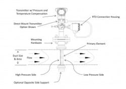
Figure 5. Averaging Pitot tube instrument with direct-mount transmitter and pressure/temperature compensation
On many units, this length of straight run cannot be found, and simply installing the instruments can be a challenge. Measurements may be needed in thin wall or fiberglass ducts, and there may be little clearance on the outside of the ducts. In such installations where the physical constraints are quite different from what a traditional flow meter would like to see, a good choice for the application is often an averaging Pitot tube (see Figure 5).
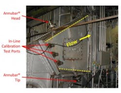
The averaging Pitot tube mounts easily in all shapes of duct, can provide a good measurement across a wide load range, has low permanent pressure loss and has a relatively low installed cost. These devices can simultaneously measure differential pressure, static pressure and temperature to calculate dynamically compensated mass flow in real-time and, perhaps most important, can be calibrated in place for unusual duct arrangements and where limited straight run is available (see Figure 6).
Figure 6. Air flow measurement in a short transition duct with ports to allow in-line calibration during setup
To calculate an optimal K factor (or flow coefficient), in-line flow calibration is used if the duct is irregular or a disturbance upstream of the flow element occurs. This involves sampling the flow at multiple points and under varying flow rates using a single-point Pitot tube. Using this technique, the true nature of the flow profile can be determined, and a reliable air flow measurement (typically, accurate to about 2 percent with good repeatability) can be obtained where it is needed on the boiler.
Oxygen measurement
The flue gas oxygen measurement at the back end of a boiler is arguably the most critical parameter used by the combustion control strategy. Managing oxygen concentration in boiler exhaust gases is important for maintaining safety and thermal efficiency. If oxygen content is too low, the combustion process will generate excess emissions or a potentially hazardous combustible mixture that is a risk for explosion. High excess oxygen results in heat loss and possibly additional carryover that can foul tubes in the generating sections of the boiler.
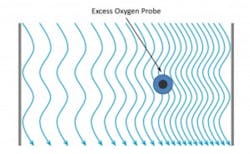
Figure 7. Flue gas stratification in the boiler exit duct may require an off-center position for the oxygen probe or the use of multiple probes.
To support an optimal combustion control strategy an in situ oxygen analyzer — a probe inserted directly into the flue gas duct without the need for a sampling system — should be used. The probe should typically be located in the middle of the duct on the boiler outlet after the generating bank and economizer but before the air heater (see Figure 7).
On larger boilers, challenges caused by tramp air and/or flue gas stratification can be encountered. Tramp air infiltration may occur on older units, causing oxygen readings to appear higher than they actually are in the furnace. When this happens, maintenance should be completed to eliminate air leakage to the best degree possible such that a relatively accurate oxygen reading is possible.
Stratification results when flue gas flow is not even across the exit duct, a situation that is not uncommon during the normal operation of bigger boilers. When this is encountered, a manual duct traverse with a handheld meter should be performed to determine the best location for measurements, and multiple oxygen probes should be considered.
The latest generation of oxygen meters is equipped with functionality such as online calibration capability, calibration diagnostics, and plugged diffuser/filter alarms (for boilers with fly ash or other particulate in the flue gas). These features are beneficial in keeping the important oxygen measurement device fully operational to the highest degree possible.
From the bottom up
To improve boiler control, working from the bottom up is important. A good base of instrumentation and end devices is required to support safe, reliable and optimal boiler operation. Focusing only on the periodic "tuning" of a boiler often results in masking field device issues that build up over time.
Many boiler measurements can be challenging because of the physical design of the process, fuel variability and other issues, but proven technologies exist to deliver desired business results. An experienced combustion process control engineer can help plant owners and operators resolve root cause measurement issues. Of course, proper combustion control strategies need to be implemented on the field device foundation to complete the control picture. Multiple factors should be considered at this level, and owners/operators should seek advice from experienced in-house or external consultants to optimize boiler operations holistically.
Bob Sabin is a consulting engineer for the Industrial Energy Solutions Group, Emerson Process Management. He has more than 30 years experience in the industrial controls engineering business including 20 years supporting boiler, steam system and energy applications. He may be reached at [email protected]. For more information, visit www.emerson.com.
