Throughout the flowmeter market, suppliers are working to address the limitations of vortex flowmeters, and they have been introducing product enhancements designed to make the meters more accurate and reliable. This article describes recent advancements such as: innovative dual-sensor technology to enhance signal frequency; advanced filtering algorithms to establish continuous, real-time norms for signal strength and quality, as well as cancel out the effect of common mode noise associated with vibration and equipment noise in piping; and rugged, one-piece welded sensor designs to eliminate failures caused by leakage over the life of the application.
Background
When it comes to measuring diverse fluids in fields like chemicals, vortex flowmeters are known for their versatility. They can measure the velocity of liquids and gases such as water, cryogenic fluids, boiler feedwater, hydrocarbons, chemicals, air, nitrogen, industrial gases and steam flowing through the pipe. One reason the meters are widely used for flow measurement of saturated steam and wet gases is they can handle liquid droplets and tolerate extremely high temperatures (see Image 1).
Vortex flowmeters were first introduced to industrial markets in the late 1970s. They utilize a physical principle that involves the formation of vortex swirls (vortices) downstream of an obstruction placed in a flowing stream. Leonardo da Vinci first observed vortices or eddies forming in fast-flowing rivers. In 1911, Theodore von Karman, a Hungarian-American physicist, did an analysis of this phenomenon, which later became known as the von Karman’s vortex street.
Vortex meters offer several key advantages, including:
- Wide rangeability
- Accuracy of +/- 1 percent of flow rate
- Repeatability of +/- quarter percent of flow rate
- Wide range of sizes and designs
- Measurement of liquids, gases and steam
- Linear output
- Availability of pulse, analog and bus outputs
Although vortex flowmeters are exceptionally versatile, they have limitations. They are generally not suitable for use with slurries or high-viscosity liquids, as well as low flow rates at which vortices do not form. Turbulent flow is required for correct operation, and strainers may be needed. The meters can be affected by pulsating flow or extreme turbulence.
Recent design enhancements
Although flowmeters that employ the vortex shedding principle have been available for decades, they are increasingly used to measure industrial flow, partly because of electronic and signal processing improvements made in recent years, as well as changes to the meter bluff body (called a shedder bar) and its interaction with the sensing system.
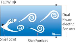
An everyday example of the vortex shedding phenomenon is a flag waving in the breeze: The flag waves because the vortices shed by air moving across the flagpole. Within a vortex flowmeter, as flowing fluid moves across the shedder bar, vortices are shed on a smaller scale. The frequency of the vortices’ shedding is proportional to the fluid velocity (see Figure 1).
With an internal resistance temperature detector (RTD), modern vortex flowmeters can compensate for changes in temperature to achieve a precise mass flow measurement. The meters are commonly designed with a piezoelectric crystal sensor to detect the pressure exerted by the vortices on a velocity sensor. The sensor converts these “pulses” into electrical signals, which are subsequently converted into a frequency by the meter electronics — allowing the instrument to determine the volumetric flow rate.
Despite the tried-and-true principle of vortex flowmeter operation, there has long been a need to improve measurement accuracy and reliability. The meters have the potential for common mode noise, vibrations, pulsations or other conditions to create false signals when employing the traditional piezoelectric approach.
Most vortex flowmeter manufacturers install a sensor in the tailpiece of the shedder bar, and every time this assembly wobbles, the flow signal is counted. However, it is essential that the tailpiece remain vertically oriented for this technique to work, which restricts the user’s installation options. Other manufacturers position a small sensor wire after the shedder bar, then account for all the vortices that bump into it. This approach can be susceptible to vibration, which can cause the tailpiece and/or sensor wire to move.
Dual independent piezoelectric sensors and advanced filtering routines can be used to minimize noise interference with vortex meters. The geometry of the dual-sensor configuration allows for signal generation with a higher frequency than many vortex technologies. The objective is to maintain signal frequency above the common mode noise typically encountered in industrial environments.
With the dual-sensor design, high sample rates and a proprietary algorithm, the sensor signals are more easily captured on both sides of the flowmeter shedder bar. Any disturbances are received simultaneously by the electronics and can be easily differentiated as non-vortex signals.
By implementing the internal RTD, the vortex meter can become a true multivariable flowmeter technology. Having the RTD for saturated steam, for example, enables the vortex software to compensate for changes in temperature, and using the standard saturated steam tables allows the meter to achieve precise mass flow measurement.
As flow increases, so does signal strength or signal amplitude in vortex flowmeters. The faster the fluid moves, the greater the impact it will have on the piezocrystal, and thus the bigger the electrical pulse generated by the passing vortices. It has always been a challenge for vortex meter manufacturers to capture the smallest signals possible without compromising the negative effects of picking up common mode noise. Today, another innovative capability, known as “threshold,” allows the vortex meter operator to adjust the electronics to accommodate a smaller signal pickup across a wider range of measurement, and in doing so, compensate for conditions such as low-flow, light gases and other fluids without affecting the issue with common mode noise pickup. This contrasts with traditional vortex meters, which lack the sensitivity to handle smaller signals and low flow without running the risk of picking up noise.
Latest metering solutions
Today’s vortex flowmeters meet a host of industrial and commercial requirements, including measurement of volumetric or mass flow rate over a large flow range. Increasingly, insertion-style vortex flowmeters are gaining popularity because of their simple installation and compatibility with large pipes.
Insertion meters are often used to measure flow in pipes that are part of continuous processes. Because they can be hot-tapped, the meters can be installed, swapped out or have parts replaced without shutting down the system, providing an added safety level in critical applications with aggressive or high-temperature flows such as those found in the chemical and power industries. Inline meters do not have this advantage unless a bypass line is installed. The latest hot tap insertion devices are also available with an insertion/extraction tool that is removable, makes installation easy under demanding conditions, and eliminates the weight, bulkiness and equipment malfunction that may occur when insertion tools are permanently connected to the meter.
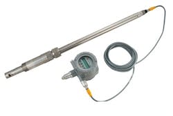
The current breed of insertion vortex flowmeters utilizes heavy-duty construction to stand up to the harshest environments inside and outside the process pipe. The meter’s lack of moving or wearing parts minimizes changes to readings over time and helps keep accuracy and repeatability constant (see Image 2).
Since shedder bar geometry is important to creating an optimal frequency in vortex flowmeters, some manufacturers have designed a one-piece solution machined from solid stainless steel bar stock. The vortex element, opening, shedder bar and tailpiece are made from a single piece of stainless steel to ensure that over the life of the application, the meter’s vortex element geometry will never shift or change shape, allowing for a long-term, repeatable instrument. When the shedder bar is horizontal, not vertical, it helps provide more room for error in shedder bar alignment. The width of a horizontally positioned shedder bar is less prone to width change when misalignment occurs. This design helps generate a precise signal frequency with velocity if alignment is imperfect. This assures vortex flowmeter operators of greater accuracy than many existing meter configurations.
New insertion vortex flowmeters also employ welded sensor technology to eliminate failures caused by leakage over time. They incorporate nonwetted sensors and have no internal O-rings or seals to allow steam or other fluids to seep into the sensors or electronic elements. This durable design with no moving parts eliminates the need for periodic maintenance. Piezoelectric and temperature sensors never touch the process fluid because they are completely enclosed and protected in the stainless steel body, giving them a long life span.
For applications where downtime must be avoided, a hot tap insertion vortex flowmeter can be installed or removed during operation — even under high pressure.
Summary
Thanks to the advent of sophisticated microprocessors, instrumentation manufacturers can utilize state-of-the-art algorithm-counting techniques to fine-tune existing vortex flowmeter technology. The current generation of dual-sensor meters, designed to produce two independent, high-frequency signals, has fundamentally changed the paradigm of vortex shedding, optimizing signal quality and noise rejection and improving overall performance in the most challenging applications.
Ryan Nice is strategic account manager for Badger Meter, a manufacturer of flow measurement and control products. Learn more at badgermeter.com.


