As ordinary as seal pots seem to a refinery or chemical plant, not all are created equal. Purchased directly from original equipment manufacturers (OEMs) with instrumentation pre-packaged, the economics that drive OEMs differ from that of end-users. For OEMs, around 25-40 percent of the cost of the seal pot can be attributed to the level device, which will significantly affect their margin. However, the moderate additional cost to the end-user for improved instrumentation can create an immediate return-on-investment (ROI). Even if not purchased upfront, end-user replacement of existing technologies with more advanced level instrumentation can yield ROI in less than one year.
The objective of this article is to understand American Petroleum Institute (API) 682 pump sealing systems, the role of level instrumentation in seal pots, potential savings and ROI over the short-term, and level solutions optimized for seal pots.
API 682 sealing systems
In the petroleum, natural gas and chemical industries, seal pots serve the fundamental purpose of fluid storage. The fluid, in this case liquid, provides protection to expensive rotating equipment, such as lubricating fluids going to the seal chamber (between the pump housing and rotating shaft) of centrifugal and positive displacement pumps. This fluid improves pump lifecycle costs by lubricating mechanical seals (friction from rotating shafts) and reducing emissions to the atmosphere through the pump shaft. Level instrumentation plays a critical role in the sealing system in terms of safety, reliability, environmental impact and cost savings.

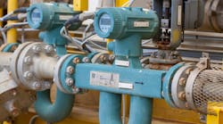
Pump sealing system. Images courtesy of Magnetrol International.
The seal pot is introduced to the pump seal chamber through various piping plans, often in compliance with sealing system standard API 682. The liquids are considered buffer fluids if the seal pot is unpressurized (Piping Plan 52). More specifically, maintained at a pressure less than the seal chamber pressure and less than 40 PSI (2.8 bar). The vapors above the buffer fluid are vented to a flare or vapor recovery system to minimize leakage to the atmosphere. If the seal pot is pressurized above the pressure of the seal chamber, then the liquids are considered barrier fluids (Piping Plan 53A). The pressurized fluid creates a barrier between the liquid and atmosphere to eliminate leakage.
Role of level instrumentation
The importance of reliable seal pot level detection, and potentially measurement, cannot be understated. Critical dynamics are at play, including worker safety, capital costs and environmental impact. Per the aforementioned standard, API 682, "It is the responsibility of the purchaser or seal vendor to ensure that the selected seal and auxiliaries are suitable for the intended service condition. It is applicable mainly for hazardous, flammable, and/or toxic services where a greater degree of reliability is required for the improvement of equipment availability and the reduction of both emissions to the atmosphere and life-cycle sealing costs."
At a minimum, low level detection is necessary to ensure liquid is present in the seal pot at all times. Loss of liquid can result in potentially hazardous conditions, costly repairs for the dry running equipment and environmental hazards due to process leakage.
High level indication may also prove beneficial. Product going back into the seal pot, raising the level, could be an early indication of seal failure. Process liquid mixed with the barrier fluid in the seal pot creates a potential safety hazard during routine maintenance due to the often corrosive or flammable process liquids found in these industrial facilities.

Seal pot with with top-mounted guided wave radar transmitter.
In terms of level measurement, seal pots have a site glass level gauge or magnetic level indicator (MLI) for local viewing. However, automation is necessary to provide alarm capabilities for the sealing system. Ultrasonic switches with relay outputs have historically been the preferred technology and are relied upon for a variety of reasons. There is no calibration required with ultrasonic switches, which benefits OEMs and end-users alike. Its performance is unaffected under varying process conditions such as density (SG), dielectric, temperature and pressure. Ultrasonic is not considered an electromechanical or vibratory type device, therefore it has high levels of reliability. Typically supplied by the seal pot vendor, these may be very basic ultrasonic switches with little available diagnostics for maintenance and troubleshooting.
Maintenance ROI
Application No. 1
Level devices are the primary equipment in the seal pot that require testing and maintenance to prevent the aforementioned incidents from occurring. If a loss of seal fluid is not indicated with a low level detection, then pump seals will eventually fail and have to be replaced. Often facilities that require additional emissions control or have stringent EH&S practices, dual seal configurations are utilized for hazardous process fluid containment.
Cost
New mechanical seals can be thousands of dollars depending on type, but a more substantial cost, potentially in the tens of thousands of dollars, is pulling the pump out of service to install the new seals and verify that other pump parts were not damaged.
Solution
Quickly catching the loss of liquid level in the seal pot is critical to prevent additional pump damage as the seals wear and eventually fail. The site will typically have a backup pump to reduce downtime while the primary pump is out of service.
Application No. 2
Performing maintenance by removing the level device from the seal pot was expensive and caused safety hazards, including a prior accident when the seal pot had accepted process liquid during a seal failure. This changes the overall density (SG) of the liquid in the seal pot, potentially causing an error in measurement if the technology is SG dependent, such as differential pressure transmitters.
The basic ultrasonic switches were upgraded to a more advanced ultrasonic model to allow push-buttons for testing purposes while in the process, eliminating the need to remove the device during testing.
Cost
Not only is this safer, but one specialty chemical end-user saved $600 per seal pot for the time and personnel necessary to pull out and test the level devices, or $1200 per year (not including prior accident cost). The number of seal pots per facility will vary by size and type of plant, but a refinery could conservatively house 200 seal pots. This amounts to a savings of $240K per year and an ROI of 7 months after installation (varies based on type of ultrasonic switch, frequency of testing, labor cost, etc.).
Solution
Advanced diagnostics may prevent maintenance personnel from removing the switches from the seal pot during routine testing. If a traditional relay output is required, then the level test push-button will change the state of the level relay and the malfunction test pushbutton will force a fault condition (malfunction relay de-energizes). These replacements also provided consistency with other ultrasonic level devices within the facility, such as ultrasonic switches being utilized for overfill protection.
Level optimization savings
The latest edition of API 682, Fourth Edition, was the first mention of transmitters for seal pot level in place of switches. However, the standard allows other technologies outside of hydrostatic (e.g., differential pressure or DP) to be utilized, including the substitution of switches in place of transmitters, effectively eliminating the requirement of continuous transmitters. It is critical that engineering, procurement and construction (EPC) firms do not over-specify the level equipment necessary for successful seal pot level detection on large new projects or expansions.
Per Annex G of API 682, "The details for each of the piping plans represent the minimum requirements of the plans. It is not uncommon, however, for users of this standard to specify slight variations to these plans. An example may be that the user specifies a level switch rather than a level transmitter. Substitutions for the instrumentation requirements in these plans are allowed (with purchaser’s approval) while still retaining the piping plan designations described in this standard."
It should be noted that ultrasonic technology can be supplied with a two-wire analog output. The current (mA) range exceeds the normal 4–20 mA process range in the event of a fault per NAMUR NE43, providing enhanced diagnostics. Push-buttons are once again available for driving a change in mA or forcing a fault condition for testing purposes without removal of the device. Additional self-test diagnostics are available during a fault condition based on LED flashes to troubleshoot the sensor, the electronics, and for environmental and acoustical noise.
There are of course positives and negatives in specifying a transmitter versus a switch. Continuous level measurement is now provided versus a discrete output, which has its benefits. Level transmitters however, particularly DP, add to the initial purchase price (compared to ultrasonic switches, which are half the cost) and involve multistep calibration procedures upon installation. There will also be added maintenance over time often due to the impulse lines. The initial purchase price, calibration and maintenance add significantly to the total cost of ownership.
An alternative transmitter to DP is guided wave radar (GWR). The primary advantages of GWR is that it is a direct measurement rather than inferred, it does not require calibration, and it is unaffected by process changes, such as those that can potentially occur during a seal failure when process liquid mixes in with the barrier fluid. Another consideration is that GWR can be extremely accurate from the bottom of the probe up to the process connection, even for shorter level spans common in seal pots, without any transition zone (or possibly dead zone).
Outside of API 682 Piping Plans 52 & 53A incorporating seal pots into the system, there is Piping Plan 53C in which the barrier fluid is pressurized by a piston accumulator. If any of these plans require the transmitter route with a local indicator, then there is an optimal design for space constraints that combines a GWR transmitter with an MLI through the same process connection.
Whether switches or transmitters are utilized, maximize ROI by selecting a technology that necessitates the least maintenance, while providing the type of safety and reliability that users in the petroleum, natural gas, and chemical industries have come to expect.
References
- American Petroleum Institute (API), API Standard 682, Fourth Edition, May 2014, Washington, D.C. API Publishing Services.
This content is sponsored by Magnetrol International. Sponsored content is authorized by the client and does not necessarily reflect the views of the Process Flow Network editorial team.