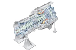
Gas turbine technology has steadily advanced since its inception, and it continues to evolve. Development is actively producing smaller gas turbines and more powerful and efficient machines. Aiding in these advances are computer-based design, specifically computational fluid dynamics and finite element analysis, and the development of new materials such as blade materials with superior high-temperature strength (for instance, single-crystal super-alloys that exhibit extraordinary strength) or thermal barrier coatings that protect the structural material from ever higher temperatures. These advances allow for higher compression ratios and turbine inlet temperatures, more efficient combustion and better cooling of gas turbine components.
The efficiencies of gas turbines have practically doubled by incorporating intercooling, regeneration (or recuperation) and reheating. These improvements, of course, come at the expense of increased initial and operation costs. The costs can be justified by a reduction in fuel costs, which offsets the increase in initial purchase and other costs. The general desire in the industry to minimize overall costs and the tremendous increase in the simple-cycle efficiency to above 45 percent left little desire to opt for further modifications.
On the emissions side, the challenge is to increase turbine inlet temperatures while reducing peak flame temperature to achieve lower nitrogen oxide (NOx) emissions and meet the latest regulations. Recently a few gas turbine manufacturers achieved turbine inlet temperatures of above 1,600°C with gross thermal efficiency exceeding 60 percent using heat recovery systems.
Turbine section
The turbine section converts the gaseous energy of the air and burned fuel mixture out of the combustor into mechanical energy to operate the air compressor and driven equipment. The turbine converts gaseous energy into mechanical energy by expanding the hot, high-pressure gases to lower temperatures and pressures. Each stage of the turbine consists of a row of stationary vanes followed by a row of rotating blades. This is the reverse of an axial compressor’s order. In an axial compressor, the rotor blades add energy to the air then convert it to static pressure by the stator vanes.
In a turbine, the stator vanes increase gas velocity, and then the rotor blades extract energy. The vanes and blades are airfoils that provide a smooth flow of gas. As the hot air stream enters the turbine section from the combustion section, it is accelerated through the first-stage stator vanes. The stator vanes (also called nozzles) form convergent ducts that convert the gaseous heat and pressure energy into higher velocity gas flow. In addition to accelerating the gas, the vanes “turn” the flow to direct it into the rotor blades at the optimal angle.
The materials used in the turbine section limit the maximum temperature at which a gas turbine can operate. The first metal that the hot combustion gases strike is the turbine inlet. The temperature of the gas stream is carefully monitored to ensure that overtemperature does not occur.
As the mass of the high velocity gas flows across the turbine blades, the gaseous energy is converted to mechanical energy. Gas velocity, temperature and pressure are sacrificed to rotate the turbine to generate shaft power. The turbine efficiency is determined by how well it extracts mechanical energy from the hot, high-velocity gases. Using properly positioned airfoils allows for smooth flow and expansion of the gases through the blades and vanes of the turbine.
All the hot air should flow across the airfoils to achieve maximum efficiency. To ensure this, internal seals are used at the base of the vanes to minimize gas flow around the vanes instead of through the intended gas path. In addition, the initial stages or sometimes all stages of the turbine blades usually have tip shrouds to minimize gas flow around the blade tips. After the gas has passed through the turbine, it is discharged through the exhaust. Though most of the gaseous energy is converted to mechanical energy by the turbine, some amount of energy remains in the exhaust gas.
Unsteady flows in gas turbines
In the turbine stage environment, the flow is periodically unsteady because of the relative motion of the blade rows. Since modern gas turbine design philosophy places emphasis on higher blade loading and smaller turbine length, the effects of these unsteady interactions are even more important.
The unsteady flow effects in a gas turbine are sources of aerodynamic noise and mechanical vibration. The unsteadiness nearly always brings a decrease in efficiency such as an increase of losses. Unsteady flows could have different effects – such as wake effects, wake-boundary layer interactions, clocking effects and hot streaks. Unsteady flows have significant effects in high-load, part-load or off-design conditions. Usually the gas turbine performance is not satisfactory during unrated conditions. Unsteady flows significantly affect gas turbine performance in these unrated conditions, such as part-load or off-design operations.
Turbine design and operation have developed to a rather high level with increasingly mature technologies. One main consideration in gas turbine design, selection, operation and reliability is flow unsteadiness during actual operation.
Traditionally, gas turbine losses have been defined as profile loss, endwall loss and leakage loss. These categories continue to be used, although loss mechanisms are seldom independent. In low-pressure turbine blades, the profile loss is generally the largest single contributor to the total loss of efficiency because of a relatively high aspect ratio of blades. The magnitude of the profile loss depends mainly on the development of the blade boundary layers, especially on the suction surfaces. The flow in low-pressure turbines is inherently unsteady because of the relative motion of adjacent blade rows. Two primary forms of periodic unsteadiness exist: the wakes from the upstream blade rows and the potential fields of blade rows both upstream and downstream. Potential interactions are weaker than wake interactions in most low-pressure turbine sections. However, small changes in the static pressure field may alter the behavior of the boundary layers that are close to separation or have separated on the rear of the suction surface of a blade. Therefore, care should be taken when dismissing the significance of potential interactions entirely. The wake interaction plays an important role in the development of the blade boundary layers and the blade profile loss.
The low aspect ratio blade has been popular in recent decades because of the increasing blade loading in medium- and high-pressure levels. The loss of the flow field in the endwall regions is inversely proportional to the aspect ratio of the blade. For turbines with low aspect ratio, losses at blade ends — including endwall loss, the loss of secondary and tip leakage flows — is a major source of lost efficiency, contributing to at least 40 percent of the total loss. Flow in high-pressure turbines is also inherently unsteady, so the unsteady effects at endwall or generally at blade ends, such as the interactions of the secondary flow vortex and tip leakage vortex with the periodic wake or potential field, is important to include in the design and operation. Moreover, in a high-loaded transonic turbine, the unsteady interactions between the shock wave and the secondary flow vortex and tip leakage vortex are also significant to these losses. To improve the performance of high-pressure turbines, focusing on the unsteady loss mechanisms in the blade-end regions (such as endwall) is necessary.
Wake effects
The wake is the region of disturbed flow (usually turbulent) downstream of a component moving relative to a fluid. The wake can be defined as a velocity deficit in the body-relative frame of reference. The wake fluid tends to be separated from the flow and not mixed. If the instantaneous velocity field is less than the undisturbed value, a wake looks like a backward-facing jet, which is called a negative jet. The negative jet in axial turbines is one of the main unsteady transport mechanisms. In an axial compressor, the pressure side presence hinders the wake transport, and as a result, the stator wake fluid accumulates on the rotor pressure side, decreasing the load on a compressor blade. Conversely in turbines, the negative jet of the wake appears to impinge on the rotor suction side, usually increasing the blade loads.
The convection of the upstream wake segment within the blade row is characterized by bowing, reorientation, elongation and stretching. Wake fluid bowing originates near the leading edge plane where the midpassage velocities are higher than the velocities near the blade surfaces. The reorientation of the wake segment occurs because of blade circulation. The velocities near the suction surface are higher than those near the pressure surface. Therefore, fluid near the suction surface moves through the passage more rapidly, resulting in wake segment reorientation. The difference in convection velocities also causes the wake segment to elongate, which decreases the wake width. Stretching occurs as the first part of the wake reaches the leading edge. The “wake avenue” is the progress of wakes through downstream blade rows. The wake segments from the rotor are arranged along a fixed path toward the downstream. Differences in the number of rotor blades in the upstream and downstream blade rows cause the downstream flow field to depend on the relative position of the upstream blade. This phenomenon could be considered as quasi-steady in the relative frame.
Wake-boundary layer interaction
In turbines, the wakes from upstream blade rows provide one source of unsteadiness. Conditions under low Reynolds numbers at low-pressure turbines, the boundary-layer transition and separation play important roles in determining turbine performance. An in-depth knowledge of blade boundary layer is crucial for the effective management and control of boundary layer transition or separation, especially the open separation, which is a key part of knowledge when designing low-pressure turbines with a low Reynolds number. Because of this, studying the wake-boundary layer interactions is important.
Periodic-unsteady transition can be caused by the impingement of upstream periodic wakes. The periodic-unsteady transition is the characteristic mode in turbines. In low-pressure turbines with a low Reynolds number, boundary layer separation may occur as the blade load increases. Rational use of the upstream periodic wakes can effectively inhibit the separation by inducing boundary-layer transition before laminar separation occurs, therefore controlling loss generation. When the wake passes, the wake-induced turbulent spots form within attached flows in front of the separation point. The turbulent spots continue to grow and enter the separation zone and, consequently, inhibit the formation of separation bubbles. The calmed region trails behind the turbulent spots. It is a laminar-like region, but it has a full velocity profile. This is known as the periodic wake-boundary layer interaction process. The flow of the calmed region is unreceptive to disturbances.
As a result, the region remains laminar for much longer than the surrounding fluid and can resist transition and separation. The combination of the calming effect and the more robust velocity profile within the calmed region make this aspect of the flow important. After the wake interaction, the boundary layer separation could occur in the interval between the two wakes.
Hot streaks
Another significant unsteady phenomenon in turbines — particularly high-pressure turbines — is the interaction of hot streaks (also called “hot spots”), which refer to the radial and circumferential temperature gradients at the gas turbine combustor exit. These pronounced, temperature nonuniformities in the combustor exit flow field are caused by circumferentially discrete fuel and dilution air injection within the combustor. The hot streaks can cause significant unsteadiness because of the relative motion of the blade rows. They interact with the different turbine parts and can locally cause increased blade heat transfer, leading to reduced blade life and significant risks.
In practical gas turbines, combustor hot streaks may have stagnation temperatures that are twice those of the free steam’s stagnation temperature. The hot streaks can lead to high heat loads and potentially catastrophic failure of the blades. Experimentally and numerically, temperature gradients, in absence of total pressure nonuniformities, have been shown not to significantly alter the flow (pressure field) within the first-stage turbine stator, but they have significant impact on the secondary flow and wall temperature of the first-stage rotor.
An important concept is the clocking effect of hot streaks. Adjusting the positions of hot streaks with respect to inlet guide vanes can help control blade temperatures in gas turbines. The impact to the blade is highest when the hot streaks impinge on the leading edge of the blade. On the contrary, the impact decreases as hot streaks deviate to have direct impingement to the leading edges. Although a thermal barrier coating or cooling can reduce the local heat load to a certain degree, either will increase the cost.
Rotor-stator interactions may also generate significant nonuniformity of the time-averaged relative total temperature at the rotor inlet. If an optimal arrangement of stators and blades exists, it may minimize the influence of hot streaks on the rotor blade’s life.
Another important concept is the hot streak surface heating. The hot streak moves at speeds significantly different than the surrounding fluid.
Turbine leakage & shroud
In a break-even tip clearance, the shrouded and unshrouded turbines have the same efficiency, and if tip clearance is less than break-even clearance, the unshrouded turbine performs better than the shrouded turbine. As a very rough indication, this break-even tip clearance could be about 0.5 percent of the rotor blade’s span for some turbines. Compared to the unshrouded turbine, the shrouded turbine can reduce the sensitivity of turbine performances to changes in tip clearance. At the given relative change in leakage flow, the relative change in work is approximately twice the relative change in efficiency. Besides, the pitch-chord ratio has a different impact on the tip leakage mixing processes in shrouded and unshrouded turbines. Lower tip leakage losses can be achieved effectively by turning the leakage flows to reduce mixing losses in shrouded turbines, and by blade tip design or tip clearance treatment to reduce the tip leakage flow in unshrouded turbines.
The possibility for the control of shroud leakage flow by modifications to the exit shroud cavity is important for gas turbines. Designers can reduce the aerodynamic losses associated with shroud leakage flow by controlling the interaction between the leakage and the main stream flow in the exit shroud cavity. The control of shroud leakage flow has been the focus in the gas turbine design with the goal of reducing the mixing losses associated with its reinjection into the main flow. Three different techniques can be used to control the shroud leakage flows: turning vanes, honeycomb bands and chamfered downstream edge of the cavity.
Turning vanes can be fixed onto the casing above the shroud and between the fins to turn the rotor shroud leakage flow in the direction of the main blade passage flow and reduce the circumferential mixing losses.
Honeycomb bands can be inserted into the casing to weaken the flow in a circumferential direction and then to reduce the circumferential mixing losses. This is effective since the honeycomb acts to kill swirl velocity development for the rotating labyrinth-honeycomb seal because of the specific hexagon structure. This affects the over-tip leakage flow and brings its velocity components closer to the velocity components of the main flow. This also reduces the circumferential mixing losses considerably compared to the labyrinth seal.
The downstream edge of the cavity can be chamfered to reduce the leakage jet radial velocity component and the separation at the downstream cavity edge and then to reduce the stream-wise mixing losses. The chamfered downstream cavity edge has the largest mixing loss reduction for all three geometries tested. The chamfered downstream cavity edge likely eliminates the separation at the downstream cavity edge and treats the leakage flow before it re-enters the main flow, which reduces the stream-wise mixing losses.
Amin Almasi is a senior rotating machinery consultant in Australia. He is a chartered professional engineer of Engineers Australia and IMechE and holds bachelor’s and master’s degrees in mechanical engineering and RPEQ. He is an active member of Engineers Australia, IMechE, ASME and SPE and has authored more than 100 papers and articles dealing with rotating equipment, condition monitoring, offshore, subsea and reliability.


