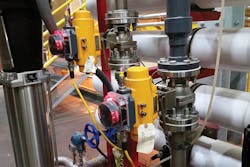
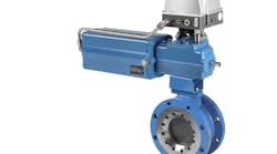
A floating ball valve is a ball valve with an unsupported ball — other than the two seats it rests on — so that the ball moves in the valve cavity to help seal off the line pressure.
The key to ball valve performance is the sealing design, regardless of whether the seats are made of metal, plastic or other material. Another important function of ball valve performance is the stem seal design. A typical floating ball valve seals off the line pressure using soft seats such as PTFE (a plastic material called polytetrafluoroethylene and otherwise known as Teflon) or TFM (a modified version of PTFE and also known as TFM 1600). TFM has a slight pressure/temperature advantage over PTFE. Both known for their fairly high temperature and pressure capabilities, PTFE and TFM are ideal choices for seat material. However, neither has a good memory; once the seat is compressed or misshaped in any way, the material will not return to its exact original shape.
How the floating ball valve works
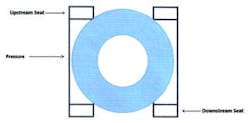
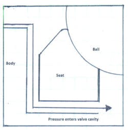
Pressure on a closed valve acts not only on the upstream side of the ball, but also on the back side of the upstream seat. The outcome of this force pushes the ball and the upstream seat in the direction of the downstream seat (see Figure 1). This force can result in both elastic deformation and plastic deformation of the downstream seat. The onset of extreme plastic deformation results in the limitations of the valve seats.
Figure 1. Pressure pushes the ball and the upstream seat in the direction of the downstream seat.
Elastic deformation is the intended temporary deformation engineered in the seat design that uses the stored energy in the design to temporarily change its shape to improve sealing performance while under pressure and temperature swings.
Plastic deformation is the permanent deformation of the seat due to compression or extreme pressures and temperatures. This is sometimes referred to as "cold flow." Again, this defines the limitations of the seat design and material.
Seating technology
There are two different types of seating technology used in floating ball valve designs: jam seat and flexible seat, which is also referred to as an energized seat.
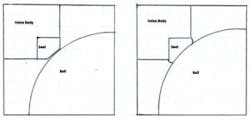
Many of the early commercial ball valve designs, as well as some used today, depend on the jam seat design. This type of sealing is created from using excess material in the seat design, thereby "jamming" the ball (during assembly) slightly into the seat, which causes the seat to be compressed against the ball and inside body wall (see Figure 2). The compression, or preset of the seat, is thereby compromising the seat due to plastic deformation. While this plastic deformation is slight, the compression of the seat is needed for tight sealing. This allows sealing in low-pressure applications, and as the pressure increases, the ball is forced into the downstream seat, causing a tighter seal.
Figure 2. Jam seat before and after preset
Also with this type of design, the seat has already formed some slight plastic deformation due to compression, so if upstream pressure is substantially increased, it will cause more plastic deformation because the ball pushes harder into the downstream seat. This is not a problem as long as the pressure remains at a high level, but if the pressure were to decrease, leakage would most likely occur because the seat would not return to its original shape — meaning that it has "cold flowed." A jam seat has no pressure compensation.
Another problem associated with jam seats is temperature swings. Thermal expansion is the general increase of volume of a material as it is heated. It is usually expressed as a fractional change in length or in volume per unit temperature change. A coefficient is applied to a given material to compare the rate of thermal expansion from one material to another. This rate is known as the material’s coefficient of thermal expansion. Normally, linear expansion coefficients are given for solids, while volume coefficients are given for liquids and gases.
In the case of increasing temperatures in a ball valve, the steel body and ball expand; however, the PTFE or TFM seats expand at a considerably higher rate — possibly as much as eight times the rate of the metal surrounding them. If the temperature change is high enough, the jam seat will generate even more plastic deformation beyond its original shape. Should the valve then become cooled, shrinkage of the additionally deformed seat would most likely cause leakage. A jam seat also has no thermal compensation.
When subject to wear, the sacrificial element in ball valves are the seats. The seats are a reasonably priced replacement; however, under high cycle conditions, jam seats wear out fairly quickly depending on shutoff pressure and valve size. A jam seat also has no wear compensation.
All plastics have a zone of elastic behavior and a zone of plastic behavior. The object is to capitalize on the zone of elastic behavior to use the stored energy, much like a diving board.
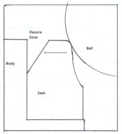
There are many different designs of the energized seat. Again, the energized seat has a way of using the stored energy engineered in the design to compensate for changes in pressure, thermal compensation and wear by taking advantage of the elastic deformation built into the design. For example, a popular design used to achieve built-in energy in the seat is to shape the internal diameter of the seat so it is flexible. Along with this design, a flexure zone is included between the valve body and the outside edge of the seat (see Figure 3). An initial preset, which takes place during final assembly of the valve, or compression is applied to the seat to cause the seat to bend into the flexure zone, thus storing elastic energy. This design takes advantage of the elastic deformation built into the design, therefore decreasing the chance of plastic deformation due to increases in pressure, thermal expansion and wear. As long as there is some clearance between the seat and the body in the flexure zone, the seat will flex rather than cold flow.
Figure 3. Flexible seat before preset
The jam seat design also uses a preset, but in that case, there is no flexure zone built into the design and uses only plastic deformation to seal.
Sealing within a floating ball valve
With both the jam seat design and the flexible seat design, in a new valve, upstream sealing will occur as long as upstream pressure does not move the ball past the effective preset. As upstream pressure increases, it forces the ball and the upstream seat to move in the direction of the downstream seat, causing the ball to press tighter against the downstream seat, which gives the valve a tight shutoff. When this happens, a gap will form between the valve body and back of the upstream seat. This allows upstream pressure to enter the valve cavity, which is exactly what is intended (see Figure 4).
Figure 4. The distance of the ball/seat movement shown above (in comparison of the size of the seat shown) is exaggerated for illustration purposes. Depending on the size of the valve and the amount of upstream pressure, the movement is actually miniscule.
There are several advantages in equalizing the upstream pressure with the pressure in the cavity; it reduces friction, minimizes seat damage and provides much lower operating torque. If the valve is automated, it would result in a smaller actuator and lower costs.
Floating ball valves are downstream sealing devices. The valve has two seats merely to make it bidirectional. This means, which either way it is installed in the pipe, both sides work the same. However, as previously mentioned, upstream sealing will occur as long as the upstream pressure does not move the ball past the effective preset on a new valve. But, as the valve wears, the effective preset of the design is lowered, thus making it easier for the upstream pressure, even at lower pressures, to enter the valve cavity.
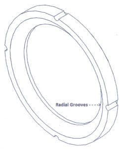
To help assist and ensure the upstream pressure enters the cavity to balance the pressure, radial grooves are slotted into the outer edge of the seats (see Figure 5). Radial grooves only effect sealing of the upstream seat because the downstream seat is forced by the ball into the internal valve body where sealing occurs on the back side of the downstream seat. Radial grooves do not make the valve unidirectional. The valve remains bidirectional because both seats are identical; the forces that occur inside the valve are also identical, keeping the valve bidirectional.
Figure 5. Radial grooves to ensure pressure balance
Thermal fluid expansion
In a floating ball valve, the cavity created between the two seats is an absolute ideal containment vessel for pressure increases. Surprisingly, there is a magnitude of pressure rise associated with temperature increases of a trapped incompressible due to thermal expansion. Ordinary water trapped without any air will increase in pressure about 100 psi for every degree in Fahrenheit of temperature increase. For example, 10˚F will raise the pressure approximately 1000 psi. And, the pressure/temperature relationship of most common liquids is approximately 90 to 110 psi per degree Fahrenheit. In fact, ANSI B16.34 Paragraph 2.3.3 "Thermal Fluid Expansion" states: "It is the responsibility of the user to provide or require to be provided, means in design, installation or operation procedure to assure that pressure in the valve will not exceed that allowed by this standard for the attained temperature."
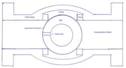
There are a couple ways ball valve manufacturers address the problem of increased cavity pressure due to thermal fluid expansion. While the valve is in the open position, any pressure in the cavity created by the ball, seats and body can easily be vented by drilling a small hole from the top of the stem slot to the ball flow path. Cavity pressure easily escapes from the cavity through the hole in the stem slot and pushes out the downstream side of the valve. However, it is much more difficult to vent the cavity while the ball is in the closed position. One way to accomplish this is to drill another hole in the ball so that when the valve is in the closed position, the vent hole is pointed upstream, thereby venting the captured media upstream while keeping the valve from leaking downstream (see Figure 6). While the vent hole is certainly a suitable way to prevent cavity pressure from building, it also makes the valve unidirectional. This is the only way that a valve using a jam seat design is capable of venting cavity pressure.
Figure 6. To prevent cavity pressure increase, place a vent hole pointing upstream when the valve is in the closed position. This, however, makes the valve unidirectional.
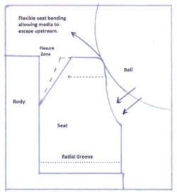
A valve using an energized seat design has the capability of the seat to flex back and forth. Cavity pressure relief will take the path of least resistance. The increased cavity pressure, now greater than the upstream pressure, will force the upstream seat to move away from the ball and flex or bend toward the upstream pressure side and vent upstream. It only takes a small amount of pressure relief for the cavity pressure to return to normal. Some manufacturers call this a "burping" effect of the upstream seat, and some refer to it as "seeping" relief. Regardless, these are self-relieving seats (see Figure 7).
Figure 7. Self-relieving seats
With that said, even the manufacturers who design their valves with self-relieving seats recommend that for high volatility duty, such as liquid chlorine, or cryogenic service, where the fluid or gas is known to possess rapid thermal expansion characteristics, it is recommended that direct discharge relief is provided using an upstream vented ball.
Conclusion
With many manufacturers in today’s growing market of floating ball valves, the floating ball valve should not be treated as a commodity. Serious consideration should be given to determine which valve is best suited for the application.
David M. Schmitt is an outside sales representative for Control-Tech Inc., an industrial valve and instrumentation distributor/representative that specializes in pressure, temperature, level and flow instrumentation as well as valves, valve automation and controls. Schmitt earned a B.S. in management with a minor in marketing from Missouri State University. He has 35 years of experience in industrial distribution of various brands of ball valves. Schmitt attributes much of his knowledge of ball valves to Joe Wright while working at Neles-Jamesbury Corporation. Schmitt can be reached at [email protected].
