Coriolis flowmeters have been around since 1977. This makes them tied with thermal as the most recent new-technology flowmeter to be brought onto the market. Magnetic flowmeters were introduced in 1952 by the Tobinmeter Company, while ultrasonic flowmeters were first brought to market by Tokyo Keiki in 1963. Eastech was the first company to introduce vortex meters in 1969. Kurz Instruments pioneered the sale of thermal flowmeters in 1977, the same year that Micro Motion released the first Coriolis meter as a laboratory instrument.
Given that both technologies came out in the same year, it is interesting to compare the Coriolis and thermal flowmeter markets today. The Coriolis market has become among the largest flowmeter type in terms of revenues, rivaled only by the magnetic flowmeter market. Both Coriolis and thermal flowmeters measure mass flow, but they do it in different ways. Coriolis meters rely on fluid momentum to deflect a vibrating meter tube, while thermal meters inject heat into the flowing stream and measure how quickly it dissipates. Thermal meters almost exclusively measure gas flow. Coriolis meters measure both liquid and gas flow, but they do a better job of measuring liquids than gases. Liquids are easier for Coriolis meters to measure than gases because they rely on fluid momentum for their measurement. Liquids are denser than gases and have more power to deflect a vibrating meter tube than gases.
Coriolis and thermal meters also differ in terms of accuracy and application. Coriolis meters are the most accurate flowmeter made and can achieve accuracies as high as ±0.05%. The accuracy of thermal meters is more typically in the 1% range. Coriolis flowmeters are widely used for custody transfer applications for both liquids and gases. They are used in upstream oil and gas applications where high accuracy is required. They are also used to measure the flow of downstream liquids, where they compete with positive displacement meters. Besides oil and gas, Coriolis meters are widely used in the chemical, food and beverage, and pharmaceutical industries. They work well for sanitary and hygienic applications.
Thermal flowmeters are also used in the oil and gas industry. One main application is their use for measuring flare and stack gas emissions. Other major applications for thermal flowmeters include measuring compressed air, wastewater treatment and natural gas submetering. While thermal flowmeters do not have approvals for custody transfer, they are used for gas applications where high accuracy is not required. Another difference between thermal and Coriolis meters is that thermal meters need to know the type of gas or gas mixture being measured, while for Coriolis meters this is not a requirement.
What’s in a name? — Thermal
The term “thermal flowmeter” is linked to its operating principle. Thermal flowmeters work by adding heat to the fluid flowing through the meter, and then measuring how quickly it dissipates. They measure the rate of heat dissipation using one or more temperature sensors. Thermal flowmeters were developed out of hot wire anemometers, which were used in research environments to measure airflow. Dr. Jerry Kurz and Dr. John Olin, who invented thermal flowmeters, did research together at TSI, Inc., in Minnesota. They worked on turbulence research and measurement of airflow in low-flow applications. The anemometers they used were not rugged enough for industrial applications. The pair developed thermal flowmeters by creating more rugged meters that could be used in industrial environments.
What’s in a name? — Coriolis
Coriolis flowmeters are named after Gaspard Gustav de Coriolis, a French scientist and mathematician who lived in the early 1800s. In 1835, he published in French an important paper called “On the Equations of Motion of Systems of Bodies.” While this paper has not previously been translated, Flow Research has had the most relevant parts of this paper translated into English. In this paper, Coriolis argues that the equations of motion known at the time did not adequately account for the motion of bodies in a rotating frame of reference. His paper was about the transfer of energy in rotating objects such as water wheels. Coriolis found a way to mathematically describe the behavior of objects that are in motion in a rotating frame of reference. He did this by adding a new term now called Coriolis acceleration to the equations of motion.
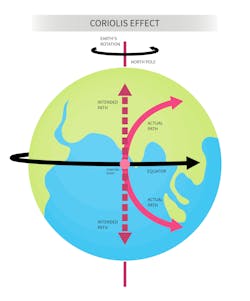
Even though Coriolis did not write about meteorology, his name today has become immortalized in weather lore through what is called the “Coriolis effect.” However, this did not happen until the early 1900s. The earth is a constantly rotating object, and meteorologists have adapted Coriolis’ logic to describe the motion of objects on or above the earth’s surface. Some examples are oceans or air currents, including low or high-pressure systems, that appear to drift sideways from their course due to the earth’s rotation. In Figure 1, this effect can be seen graphically. If a ball is thrown hypothetically from the equator to the North Pole, following the dotted line in the center, it will appear to curve to the right even if it is thrown in a straight line. This is because the earth is rotating beneath the ball, causing it to miss its intended target. The same example is illustrated by using a merry-go-round as the rotating frame of reference. If a child throws a ball at Horse 1 on the merry-go-round, it will be more likely to strike Horse 2, the next horse in the circle. This is because the merry-go-round is rotating under the ball as it is thrown.
Application to Coriolis flowmeters
Even though Coriolis flowmeters did not appear on the market until 1977, there was a lot of patent activity relating to Coriolis meters in the 1950s and 1960s. Some of these patents referenced the Coriolis force rather than the Coriolis effect. A patent in April 1958 appears to be the first patent that mentions the “Coriolis force.” It was filed by Roby B. White on behalf of American Radiator & Standard Sanitary Corporation and is called “CORIOLIS MASS FLOWMETER”. The flowmeter is described as follows:
The present invention relates to instruments for measuring the mass rate of flow of fluids and in particular to an improved flowmeter of the type in which mass flow rate is made responsive to Coriolis force… In instruments of the class described the fluid to be measured is subjected to tangential acceleration in a whirling tube, or impeller, the torque exerted on the tube in reaction to the Coriolis force of the accelerated fluid being measured as an indication of the mass flow rate.
It is important to note that this patent describes a whirling tube, meaning it is actually rotating like an impeller. This patent also proposes using the torque exerted on the tube to derive mass flow.
Yao Tzu Li patented an invention in May 1960 called “MASS FLOWMETER” that involves rotating the flow:
The present invention operates by causing the fluid to be rotated as it flows radially outward from an axis. This produces a Coriolis acceleration in the fluid, and therefore a Coriolis force is applied by the fluid to the member through which the fluid flows. This force is measured, and the mass rate flow of the fluid is obtained.
In November 1965, July 1967, and December 1967, Anatole J. Sipin patented three separate devices designed to measure mass flow. These designs were intended to improve on earlier designs that involved rotating the flow or using an oscillating gyroscope. Sipin’s objection to rotating gyroscopic designs was that they required rotating fluid seals, which introduced potential leakage and friction problems. His objection to oscillating gyroscopic designs was that they involved bends and turns that made the meter difficult to clean.
In August 1972, James E. Smith patented a “Balanced Mass-Moment Balance Beam with Electrically Conductive Pivots.” Beginning in August 1978, James (Jim) Smith began patenting a series of devices that became the basis for the flowmeters produced by Micro Motion. His August 1978 patent was filed in June 1975 and references two of Sipin’s earlier patents. These patents explicitly evoke the Coriolis force. Jim Smith founded Micro Motion out of his garage in 1977. In 1981, Micro Motion introduced its first single bent tube Coriolis flowmeter, although the company introduced its first Coriolis meter in 1977, designed for laboratory use (the A Meter).
How to describe the motion of a Coriolis flowmeter
The above quotes from 1958 and 1960 show that these patents proposed flowmeters in which the fluid is accelerated in a rotating tube (1958), or in which the fluid is actually rotating (1960) and say that this movement produces Coriolis forces. In Jim Smith’s patents, he substituted a vibrating and oscillating tube for a rotating tube. This design worked much better than the earlier ones and is still used today in many different forms.
Many experts who explain the Coriolis principle say that the meter body containing the fluid actually rotates. However, Dalian Yoke, a Chinese manufacturer of Coriolis meters, has a different take: “It is difficult to generate Coriolis force by rotating motion. At present, products are all produced by pipe vibration, that is, a thin-walled measuring tube fixed at both ends is excited by the resonance of the measuring tube at the midpoint or a frequency close to resonance. The fluid flowing in the tube generates Coriolis force, which makes the two halves before and after the midpoint of the measuring tube bend in opposite directions. Electromagnetic methods are used to detect the amount of deflection to obtain the mass flowrate.
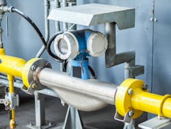
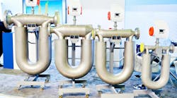
This is a good statement of the Coriolis principle of operation. A Coriolis meter consists of one or two flowtubes usually mounted in a U-shaped pattern, along with a transmitter. Electromagnetic exciters cause the tube(s) to oscillate, or swing back and forth. To make the mass flow measurement, pickoffs are mounted on the flowtubes. Each pickoff contains a coil and a magnet. As the coil moves through the magnetic field from the vibration of the tubes, voltage is produced. This voltage produces a sine wave. The sine waves generated indicate the motion of one tube relative to the other.
Mass flowrate can be determined by comparing the sine waves generated by the inlet and outlet pickoffs. When no flow is present, there is no time difference between the two pickoffs. As flow begins in the tubes, a time difference develops between the inlet and outlet pickoffs. The higher the flowrate, the greater the time difference. This time difference, also called a phase shift, is directly proportional to mass flow.
Those who believe that Coriolis forces are at play in Coriolis meters say that as fluid moves through the flowtubes, Coriolis forces are generated in the flowtubes, causing them to twist in opposition to each other. One might also say that as fluid moves through the flowtubes, the inertial force of the fluid causes the tubes to oscillate. It seems that to create a working meter, engineers have abandoned rotation of tubes or fluid in favor of vibration and oscillation. Yet some counter that oscillation is a form of rotation.
The Coriolis force is defined as follows: Fc = 2M ωxv
Here is the Coriolis force applied to a vibrating tube:
Here Fc = the Coriolis force
ω = the angular velocity of the tube as it vibrates from one side to the other
M = Mass flow
V = velocity of the fluid inside the tube
The key term here is angular velocity, which Coriolis talks about in his 1835 monograph. This is a direct tie-in with Coriolis’ equations in that paper in which he introduces the idea of what is now called “Coriolis acceleration.”
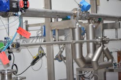
One way to reconcile the question about whether a Coriolis rotates or merely oscillates is as follows. Early inventors in the 1950s and 1960s such as Sipin and others designed flowmeters that actually rotated the tube or the fluid. Later inventors such as Jim Smith and Don Cage realized that these designs were impractical and substituted oscillation and vibration for rotation in their Coriolis designs. They then went through a period of trial and error as they tried to come up with an optimal Coriolis design. Since that time, dozens of different tube designs have been patented and built, with varying success. Endress+Hauser (1987) and KROHNE (1984) have added a straight tube meter to the mix.
Today many proponents of Coriolis flowmeters continue to maintain that Coriolis meters actually rotate, even though it seems that rotation has been replaced by vibration and oscillation. Their argument seems to be that oscillation is a form of rotation because if oscillatory motion is extended to a full circle, it can be seen as rotation. This interpretation may be correct, but it is not the only way to look at the situation.
Perhaps vibration and oscillation require their own analysis independent of rotation. The fact that Coriolis’ concept of angular momentum appears to work to analyze the motion of vibrating and oscillating tubes does not prove that these are forms of rotation. It may only show that Coriolis’ analysis of rotational motion actually applies to other types of motion besides rotational motion. Perhaps it can apply in other contexts where there is an accelerating frame of reference, or where motion is curved but not circular. Even the earth is not round like a sphere; it is a spheroid, and is flattened at the poles. If this is so, Coriolis’ theory is broader than it is generally regarded as being.
A parallel problem exists in measuring fluid flow in round pipes. Many pipes are not perfectly round, yet we typically use the equation for the area of a circle — π x r2 — to calculate the area of a round pipe. Yet Morgan Industrial Technology tells us that perfectly round pipes do not exist: “The perfect pipe does not exist — no matter what the manufacturer tells you. The smallest variations in length, wall thickness, and ovality make this impossible.”
It may be that these variations are too small for people to care about, but it is hard to believe that they never matter. If someone is running thousands of gallons or liters of a high-value product through a round pipe, and the pipe is even slightly out of round, then the calculated fluid volume may not equal the actual fluid volume. A similar problem exists with build-up inside a pipe, which can alter both the inside diameter and the area of the pipe. Both values are crucial in calculating flow through a pipe. And no matter how accurate a flowmeter is, its measurement won’t be truly accurate if the values used to compute the flow are inaccurate.
The basic concepts of our mathematics have not changed in 2,500 years, despite the development of calculus and advances in set theory. We have been taught to believe that mathematics is about ideal objects like perfectly round circles and not about imperfectly round pipes and out of round spheroids like the earth. Perhaps it is time to take a fresh look at our mathematics.
Dr. Jesse Yoder is president of Flow Research Inc., a company he founded in 1998. Dr. Yoder has 35 years of experience as a writer and as an analyst in process control and instrumentation. He has written more than 280 market research studies, most of them regarding flow and instrumentation. Dr. Yoder has also written more than 300 articles on flow and instrumentation for trade journals. Many can be found at www.flowarticles.com.
For more on Flow Research’s work in the area of Coriolis Flow Measurement, visit www.flowcoriolis.com.
Flow Research


