Safety instrumented systems are designed to be the last layer of defense, with their primary functions being to bring a process to a safe state and prevent safety incidents from occurring. This significantly differs from the basic process control system, which is designed to keep the process running efficiently. Even under the best of circumstances, accidents can and do occur. However, properly designed and implemented safety systems help reduce the frequency and/or severity of incidents. A major part of proper implementation and verifying installed performance includes the proper testing of equipment to ensure functionality in case of a safety demand. Choosing instruments that utilize advanced diagnostics and testing procedures can provide additional diagnostic coverage to ensure safety while reducing process downtime.
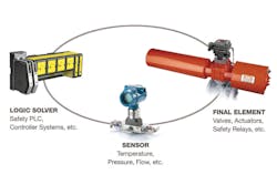
Figure 1. Components of a safety instrumented function.
Basics of probability of failure on demand & proof testing
A safety instrumented function is comprised of the logic solver, sensor(s) and final element(s) (see Figure 1). To reduce the level of process risk to an acceptable level, the safety instrumented functions must be designed and products must be selected to meet a desired safety integrity level (SIL) target. Meeting the SIL level target can be achieved based on ensuring that systematic capability, probability of failure on demand (PFDavg for low-demand mode of operation) and minimum architecture constraints meet the minimum SIL level required. Proof testing can have a direct impact on the PFDavg and is an area that can be optimized to better ensure safety compliance.
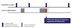
Figure 2. PFD quantifies the risk that a loop component required to bring the process to a safe state is simultaneously in failure mode.
Probability of failure on demand (PFD) describes the risk of a safety instrumented system component being in a failure mode when it is also required to bring the process to a safe state. The case that a safety demand occurs simultaneously with a component failure can have dangerous results because it prevents the safety instrumented system from mitigating the hazardous event (see Figure 2). PFD (PFDavg for low-demand systems) is calculated by combining each component’s number of dangerous failure rates as well as considering mission time, proof test intervals, effectiveness, mean time to restore, redundancy and other variables. Failure rates are quantified as failures in time (FITs) of the safety instrumented function elements.
Proof tests are operational tests conducted in accordance with an individual product’s safety manual that test the component’s ability to perform its safety function and uncover dangerous undetected failure modes. Dangerous undetected failures are failures that prevent the device from performing its primary function and remain undetected by the device during normal operation. Proof test intervals are the frequency of time between when proof tests are conducted. The frequency of these tests is determined by using the PFDavg calculation. Also, as stated by functional safety standard IEC 61511, the entire safety instrumented system (sensor, logic solver and final element) must be tested, and at some periodic interval the frequency must be re-evaluated.
Simplified PFDavg calculations may assume perfect proof test effectiveness (the proof test’s ability to diagnose 100 percent of dangerous undetected failures), but perfect proof tests are extremely rare in reality. Proof test effectiveness will depend on the test’s rigor. Some important tests such as valve leak tests may not be reasonable to perform unless the unit is shut down since testing may require removing equipment from service or significantly altering the process output. A reduction in proof test effectiveness will shorten the proof test interval time to achieve the target PFDavg or SIL, causing more process downtime. The increased test frequency could potentially also increase personnel exposure to hazards and increase the odds of human error.
How to optimize proof test intervals
Proof test intervals can be optimized by maximizing proof test effectiveness in several ways: utilizing different proof test options as provided by the manufacturer, proof tests utilizing automatic diagnostics, as well as supplementing proof tests with additional in-service or in-situ tests, such as a final element partial stroke test.
Some product manufacturers define multiple proof test options that vary in effectiveness. Generally, the more thorough the test defined, the greater the effectiveness.
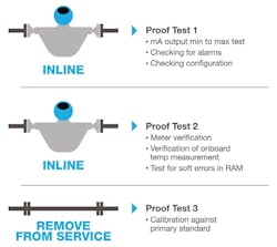
For example, a Coriolis meter might have three levels of proof tests:
- Proof Test 1 – Checks the transmitter outputs, alarms and configuration with an effectiveness of 50 to 60 percent (meter remains inline)
- Proof Test 1, 2 – Includes test outlined by Proof Test 1 plus additional advanced diagnostics like meter verification (a check of the sensor and electronics), verification of the temperature measurement and a soft test of RAM with an effectiveness in the low 90 percent range (meter remains inline)
- Proof Test 1, 3 – Includes test outlined by Proof Test 1 plus calibration against a primary standard with an effectiveness around 99 percent (requires removal of meter)
Users can choose to use advanced diagnostics such as meter verification to extend the interval between the comprehensive proof tests (Proof Test 3) to reduce operational interruptions and decrease the cost of proof testing (see Figure 3).
Automatic diagnostics can also be valuable in reducing dangerous undetected failures on a continuous basis. For example, a simple feedback loop on the milliamp output enables a device to continuously check that the output intended to be sent from the transmitter is the actual value being sent. Additional diagnostics can target specific dangerous undetected failures outside of the device, such as plugged impulse piping with pressure instruments. This diagnostic can monitor for plugging in the impulse line and send an indication to the control room so this failure mode can be corrected and the potential for failure can be limited.
Additional testing can be performed to supplement proof tests and either improve SIL capability or safely extend the time between proof tests. Partial stroke testing (PST) is a prime example of a test that can be used to extend the time between proof test intervals. Proof testing the final element is especially important since the final element is considered the weakest link of the safety instrumented function. This is primarily because it remains in one position while in contact with the process fluid for most of its lifetime.
Proof testing of the final element typically includes stroking the valve over its total travel as well as measuring seat leakage and safety time. It is disruptive to the process, so proof testing is either performed out-of-service or in-service with a bypass engaged. Users with out-of-service proof tests that do not align well with maintenance interval timing, or with applications more prone to stiction may need a solution to extend time between proof testing by additionally exercising the final element while in service.
A portion of dangerous undetected failures can be uncovered with partial stroke testing of the final control element. The level of diagnostic coverage depends on the test conducted and the information gathered. Simple PSTs, such as those performed by a mechanical jammer or solenoid trip with limit switches that detect PST position, can detect obvious cases of failure modes like valve stuck or slow to move. These cases are contributed to by specific failure modes such as valve shaft is stuck, valve packing is seized or tight or when the actuator air line is crimped or blocked.
Simple PSTs may only cover a portion of the final control element, typically the actuator. Because this limits the diagnostic coverage, the effort to perform a PST may not be worthwhile. Intelligent valve instruments with pressure and travel sensors, such as digital valve controllers, can identify failure modes detected by a simple PST. Additionally, they can calculate and alert on friction changes, breakout force required to operate the valve and stiction prior to failure. This tests the valve and actuator, rather than just one of them. Some intelligent instruments can also facilitate the testing of the entire final element, including solenoids and other accessories.
Utilizing optimized methods to perform proof testing, such as manufacturer proof test options, automatic diagnostics and in-service/in-situ testing are easy ways to increase diagnostic coverage of otherwise dangerous undetected failures. Extending the time between proof test intervals and, in the case of sensors, not requiring instrumentation to be removed from the process, decreases plant downtime, improves output, reduces personnel exposure and chance for human error without sacrificing SIL capability and functional safety.
Erik Mathiason is a product manager at Emerson responsible for Rosemount products. He has been with Emerson since 2010.
Tonya Wyatt is a senior product manager at Emerson responsible for Micro Motion Coriolis transmitters. She has been with Emerson since 2000.


