Enhancements to turbine flowmeters extend their measurement performance capability for applications that did not exist in the past. They remain one of the most durable, reliable and accurate flow instruments serving the market.

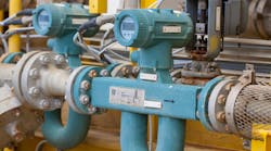
Image 1. Dual rotor turbine flow meters provide extended performance not obtainable with traditional single rotor meters. Graphics courtesy of Badger Meter
The turbine meter rotor spins in proportion to the fluid velocity passing through a known cross sectional area of the meter housing. Because the velocity is directly proportional to the volumetric flow rate, the speed of the rotor’s rotation is also directly proportional to the volumetric flow rate.
Turbine flow meters incorporate a time-tested measuring principle that can be used for both liquids and gases. More recently, flowmeter designers developed turbine meters that use a dual rotor configuration in response to evolving industry requirements for wider operating flow ranges, enhanced repeatability, superior absolute accuracy and less costly installation. Empirical data has shown that these meters provide extended performance not obtainable with traditional single rotor meters (see Image 1).
This article describes how the latest advancements in dual rotor turbine flowmeter technology have optimized measurement performance; simplified installation; and reduced costs in a wide range of industrial, aerospace, automotive, and test and measurement applications.
Principle of operation
The dual rotor turbine flowmeter design employs two closely coupled rotors that turn in opposite directions. The flow exiting from the first rotor greatly affects the inlet incidence angle on the rear rotor, hydraulically coupling the two rotors. Fluid swirl conditions on the first rotor have an opposite effect on the second rotor. If the front rotor slows down due to swirl effect, the rear rotor will speed up by the same percentage. The inverse is also true. If the front rotor speeds up, the rear rotor will slow down.

Image 2. The configuration of the dual rotor turbine meter enables measurement across a wider flow range.
Dual rotor meter users know that the sum or average of its rotors represents the actual flow rate, regardless of swirl effects on rotor revolutions per minute (RPM). Therefore, flow straighteners are not required in most applications; these include upstream/downstream straight pipe runs that are intended to eliminate flow distortions that degrade instrument performance. This makes it possible to install the flowmeter in limited spaces where the added length of piping cannot be tolerated.
When using flow straighteners, monitoring the frequency output ratio of Rotor A and B provides bearing diagnostics. Bearing contamination is easily determined if a flow processor detects an output frequency ratio shift. Bearing diagnostics can note anomalies when securing test data over long periods of time, or while the meter is used on the ocean floor in a subsea pod application.
The increased incidence angle onto the second rotor of the dual rotor turbine flowmeter enables measurement over a wider flow range. Obviously, the advantage is that one dual rotor meter could cover the range of two single rotor meters. Using this technology can eliminate applications for dual manifold systems, saving the cost of actuator valves and dual channel flow processors (see Figure 2).
Latest technology advancements

Image 3A. Three 90-degree elbows out of plane without any flow straighteners
A key feature of the dual rotor turbine flowmeter design is its ability to enhance universal viscosity curves (UVC) and extend the usable measurement flow range. A greater incidence angle on the second rotor makes it possible to measure lower flow rates, increasing the turndown capability. This significantly extends the meter’s flow range for UVC plots and single viscosity applications.
To further enhance meter performance, helical rotors have a lower pressure drop and provide an even distribution of force across the entire rotor and bearing system. This improves repeatability and reduces bearing wear, although with today’s ceramic bearings, contamination is more likely than bearing wear.

Image 3B. Piping configurations for dual rotor "flow swirl" tests show two elbows, with and without downstream flow straightener
Dual rotor turbine flowmeters with a secure clamping system for internal components can maintain a repeatability of ±0.02 percent because they prevent movement that could potentially change the flow profile. This clamping system is desirable for bidirectional flow and provides a solution for high-shock applications.
Sophisticated flow processors, along with associated sensors, help maximize flow measurement accuracy with proven compensation techniques. The flow processors also handle dual frequency input to accommodate the dual rotor turbine flow meter, bearing diagnostics and blade averaging/smoothing.
Dual rotor turbine flowmeters have a repeatable flow range of up to 500:1 and a UVC turndown range of 60:1, which is in contrast to 100:1 and 10:1, respectively, for many single rotor turbine meters. With this, the user can deploy fewer meters to cover a wide range of flow. It also lowers the initial purchase cost and simplifies system integration and future maintenance.
Testing confirms benefits

Figure 1. Rotor A and Rotor B calibration comparison, which shows an opposite reaction to swirl effects
Recently, extensive flow swirl tests were conducted on a primary standard flow calibrator to produce data that confirms the advantages of dual rotor turbine flowmeters. Calibrations on a 1-inch meter used a positive displacement liquid calibrator with fluid viscosity temperature correction capabilities.
The piping configuration for the calibrations used 90-degree elbows in two locations (entrance and exit), as well as a worst case scenario with three 90-degree elbows out of plane. Tests were run with and without a downstream flow straightener to mitigate the chance of any cancelation effect from a symmetrical piping configuration. The calibration fluid was Stoddard solvent (1.12 centistokes), with flow rates ranging from 0.15 to 65 gallons per minute. Data were collected across a turndown range of 433:1 and plotted in a Strouhal-Roshko format (see Image 3).
The calibration plots in Figure 1 clearly show an opposite swirl effect between the Rotor A and Rotor B flow meter outputs. By summing both rotors, the swirl effect cancels out, and the result correlates with the calibrator flow rate less than ±0.5 percent of the reading. The downstream flow straightener had no affect on the output. Rotor A by itself could be interpreted as the performance of a typical single rotor meter (see Figure 1).

Figure 2. The summation of Rotors A and B confirms that flow straighteners are not required with dual rotor flow meter technology.
The calibration data confirms that no flow straighteners are required with a dual rotor turbine flowmeter. It also proves that the technology can be installed in environments with less-than-ideal piping geometry, such as automotive test stands with cramped components, aircraft platforms where space is at a premium, original equipment manufacturer applications in which enclosures or skids limit piping length, and existing flow meter applications with incorrect flow straightener design lengths (see Figure 2).
Conclusion
Dual rotor technology has enlarged the turbine flowmeter’s application envelop with improved accuracy, which is not feasible with single rotor technology. By eliminating the need for flow straighteners, dual rotor meters reduce costs and make placing installations in limited spaces possible. The meters’ extended flow range can eliminate the use of dual meter manifold systems. With the added capabilities of helical rotors, ceramic bearings, bearing diagnostics, secured internals and advanced flow processors, these instruments open opportunities in applications that could not be achieved before without compromising accuracy.

Ron Madison has been involved in instrumentation his entire career and has knowledge of flow measurement technologies and applications. Currently employed with Badger Meter, a flow meter manufacturer, he continues to pursue flow measurement solutions. Madison may be reached at rmadison@badgermeter.com or 480-285-8323.