Variable speed drives (VSDs) are designed for many different environments. Installations in industrial applications can be some of the harshest. The drive must be designed from the heatsink up with many different applications in mind. The drive has been designed to deal with different climates, power sources, motor types and distances while being operated from a local control panel, fieldbus or discrete input/output (I/O). This article details best practices for trouble-free operation of the drive and application in the location in which it is installed.
Consider the following:
- Mechanical — Is an enclosure needed for the environment in which the drive is installed?
- Input power — What is the power source and how stable is the source?
- Motor wiring that powers the motor
- I/O — Wiring installed and routed to control the application
- Fieldbus wiring for control and monitoring without interference
When selecting VSDs, many aspects are reviewed. The product must be able to run the motor without interruption whether it runs for minutes, hours or 24/7, 365 days per year.
Ideally, an engineer could design the application from the ground up and all the necessary components would be considered, but this is often not the case. New installations in existing facilities, retrofits and upgrades take place every day. The following information helps provide the best opportunity for trouble-free operation.
First consider installation mechanics. This article assumes the drive is sized for appropriate control of the motor and application (voltage, power, response time and I/O needs).
Temperature
Minimum and maximum ambient temperature limits are specified for all adjustable frequency drives (AFDs). Avoiding extreme ambient temperatures prolongs equipment life and maximizes system reliability. Component life is affected by heat, dust and humidity. Controlling these variables will extend component life and lead to longer drive life.
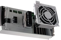
AFDs have built-in fans for optimal cooling. The main fan forces air flow along cooling fins on the heatsink, removing the heat as efficiently as possible to keep power components from overheating. Some power sizes have a small, secondary fan close to the control card to circulate air and avoid hot spots. The main fan is controlled by the AFD internal temperature and the speed gradually increases along with temperature, reducing noise and energy consumption when need is low. It ensures maximum cooling when necessary.
In environments with extreme temperatures, additional steps may be needed to maintain the proper ambient temperature. Additional cooling fans, air conditioners or heaters may be required.
Altitude
Air cooling capability decreases at lower air pressure. Manufacturers provide guidelines on handling situations such as approaching higher elevations above sea level. For example, below 3,300 feet (1,000 meters) altitude, no derating is necessary, but above 3,300 feet (1,000 meters) steps need to be taken. Typical steps are to derate (reduce the current rating) the drive or add additional cooling. In addition to the decreased cooling, the air gap between components becomes less and an arc can occur without proper spacing.
Humidity
Although the AFD can operate properly at high humidity (up to 95 percent relative humidity), condensation must be avoided. Moisture in the air can condense on electronic components and cause short circuits, particularly when the AFD is colder than moist ambient air. Condensation can occur on units without power. It is advisable to install a cabinet heater when condensation could be caused by ambient conditions. Avoid installation in areas subject to frost. Alternatively, operating the AFD in standby mode (with the unit connected to line power) reduces condensation risk. However, ensure power dissipation is sufficient to keep the AFD circuitry free of moisture.
Dust & particulates
Installation of AFDs in environments with high dust exposure is often unavoidable. Take into account three aspects when AFDs are installed in such environments:
- Reduced cooling — Dust forms deposits on the device surface and inside on circuit boards and electronic components. These deposits act as insulation layers and hamper heat transfer to the ambient air, reducing cooling capacity. The components become warmer, causing electronic components to age faster and the unit service life to decrease. Dust deposits on the heatsink in the back of the unit also decrease service life.
- Cooling fans — Air flow for unit cooling the unit is produced by cooling fans, which are usually located on the back of the device. Fan rotors have small bearings into which dust can penetrate and act as an abrasive. This leads to bearing damage and fan failure.
- Filters — High-power AFDs have with cooling fans that expel hot air. Above a certain size, these fans are fitted with filter mats. These filters can become quickly clogged in extremely dusty environments. Preventive measures are necessary.
Under these conditions, it is advisable to clean the drive during periodic maintenance. These fans are critical to the life of the drive. Remove dust off the heatsink and fans and clean the filter mats.
Rain, snow & sun
Some installations require equipment to be installed outdoors. The enclosure should be designed to handle harsh winters; hot summers; rain; critters; bugs; and direct sunlight. The temperature needs to be kept within the limits reviewed earlier. Direct sunlight can create hot spots. Rain and snow need to stay outside the enclosure. Animals and bugs will look for hiding places. Selection of the right protection class and options for the environment ensure continuous operation.
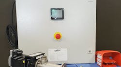
Figure 1. Select the drive and motor that will work for the application. VLT drives are motor-independent.
Spacing
Space around the AFD allows air to circulate through and around it for proper cooling. The manufacturer provides recommendations for space above, below and on the sides. In some instances, drives can be mounted side by side with no space around them.
Aggressive gases such as hydrogen sulfide, chlorine or ammonia can damage AFD electrical and mechanical components. Cooling air contamination can cause gradual decomposition of polychlorinated biphenyl tracks and door seals. A clear sign of an aggressive atmosphere is corroded copper. In aggressive atmospheres, enclosures and conformal-coated circuit boards are recommended.
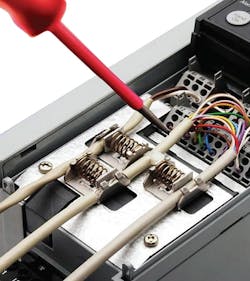
Image 2. Properly route and connect control cables to ensure a high-quality signal.
Vibration
Vibration, shock or seismic requirements can be overlooked during installation. AFDs are tested against shock, vibration and possibly seismic activity. Shock, repetitive motion or vibration can cause connections to become loose, components to break away from circuit boards or mounting hardware to stress and fail.
Enclosure types
To handle the conditions listed, manufacturers provide options to enclose (protect), cool or heat equipment as needed.
Standard enclosures include UL or NEMA Type 1, 12 and 3R. Some manufactures offer higher protection class drives. Some products are certified for Class I, II and III; Division 2, Groups A, B, C, D, F and G. These areas need an extra degree of protection because they contain dust, water or explosive gases.
Power wiring
Input power — Distribution network, voltage & line disturbances
Understanding the power source (230, 460, 600 volts) is critical when selecting a VSD. In some remote locations, only single-phase power is available, which requires a special design. In new designs, this information is readily available.
Key areas are to investigate are:
- Voltage level — Select the appropriate drive for that voltage and single-phase or three-phase.
- Transformer configuration — Does the transformer have a solidly grounded secondary? If not, the drive may have metal oxide varistors or filter caps that need to be removed.
- Do power quality issues exist? — This may require the use of a drive with a direct-current choke or line reactor built in or the use of an external reactor or isolation transformer.
When wiring cables for input power, size wiring based on the AFD’s input current and comply with local and national electrical codes. Because these cables carry high voltage, they should be kept away from control wiring, other power wires and motor wiring to avoid inducing voltages in other cables.
Motor wiring — Grounding, shielding
Wire used between the drive and the motor should be reviewed. In a retrofit when replacing a starter or contactor with the drive, consider that motor wiring in the past may have been individual conductors in a conduit. VSDs use insulated-gate bipolar transistors to the drive output to control a motor and vary speed. The cable must be sized correctly and designed for its installation location. Along with the cable, the right drive and motor combination is needed. Consider if the environment has moisture, oil or potential for the cable to be crushed to select the appropriate cable and if a specific conduit is needed.
The best cable to use is one designed for VSDs. This cable will provide the necessary conductors for the motor: a ground and a shield. Grounding and the use of the shield are vital when it comes to higher frequency switching at output terminals. Grounding is done for safety and provides a path from the motor back to the drive using single-point grounding. This means the ground conductor is connected at the motor and to the ground terminal on the drive. This single-point grounding technique is designed to keep the high-frequency noise generated between the drive and the motor so it does not spread to other equipment.
For drive installation on an older motor, an output reactor and a dV/dT filter are recommended to protect the motor from peak voltages that can occur at motor terminals because of reflected waves.
Induced voltage
Induced voltage from output motor cables that run together can charge equipment capacitors even with equipment turned off and locked out. Failure to run output motor cables separately or use shielded cables or metal conduits could result in death or serious injury. Remember to:
- Run output motor cables separately or use shielded cables or metal conduits.
- Comply with local and national electrical codes for cable sizes.
- Follow the motor manufacturer wiring requirements.
Control wiring — Digital & analog I/O, fieldbus, STO & encoder
Control wiring integrity is critical. The control wiring for digital and analog signals, fieldbus cables, safety circuits and feedback devices require shielded cable and separation from power and motor wiring. If control wiring needs to cross power or the motor, do so at a 90-degree angle.
Choose wiring designed for the signal carried, voltage and current rating. Use the shield to protect against crosstalk.
The cable from a remote, mounted control panel is often overlooked. This cable needs to be routed away from power and motor wiring as well.
Best practices
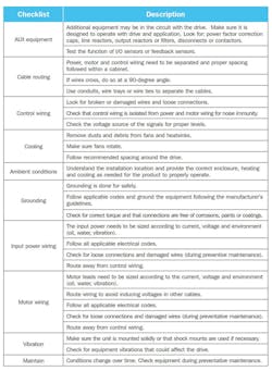
Manufacturer recommendations and manual instructions provide the best installation and the best opportunity for trouble-free operation. If a deviation occurs, use the checklist to run through each installation area. Some areas may not apply or can be changed because of cost or how and where they are installed. Try to reduce the amount of deviation from the manufacturer’s recommendations and follow local and national codes for installation and wiring.
Jim Kluck is senior product marketing manager for Danfoss Drives. He can be reached at [email protected] or 414-514-1255.
