Editor’s note: Part 1 of this two-part series focuses on axial flows and design details of axial compressors. Look for Part 2 in our next issue.
In an axial compressor, the compressed gas principally flows parallel to the rotation axis. Axial compressors have the benefits of high efficiency and large flow rates, particularly in relation to their sizes and cross sections. They offer the most compact and lightweight compressor design for large volumes and the lowest cost per flow rate for large flow rate applications. They do, however, require several rows of blades (axial stages) to achieve large pressure rises, making them complex and fragile relative to other compressor designs such as centrifugal compressors. They are expensive machines, but the cost per flow rate for large flow rates could be lower than that of other compressor types. Axial compressors have been used in many industrial applications such as large volume natural gas services, large volume air separation units, fluid catalytic cracking, propane dehydrogenation, large refrigeration units, large volume process gas services and many more, particularly anywhere compression of large flow rates is needed.
As a rough indication, axial compressors are used in flow rates from 100,000 to 1,500,000 cubic meters per hour. The pressure ratio could be between four and 27. These are rough capacity and pressure ranges. Some modern axial compressors can offer pressure ratios of around 40 in large volume ranges, but they are only used in special applications.
As an indication, axial compressor manufacturers can usually offer six to 11 standard frame sizes that are each available with four to 21 stages. A required axial compressor should usually be selected from these available frames. The pressure ratio is usually determined by the number of stages. The flow of each frame is most often varied by changing the length of the blades.
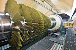
Axial compressors consist of rotating and stationary components known as blades and stators, respectively. A shaft drives a central drum retained by bearings, which has several annular pairs of blades and stators. Each pair has one blade (rotating) and one stator (stationary) and such a pair is also known as a stage (or axial stage). The blades accelerate the gas. Stators are attached to the compressor’s stationary tubular casing. The stators, also known as vanes, convert the increased rotational kinetic energy into static pressure through diffusion, redirecting the flow direction of the gas and preparing it for the rotor blades of the next stage. The cross-sectional area between the rotor drum and casing is reduced in the flow direction to maintain an optimal Mach number using variable geometry as the gas is compressed.
Industrial axial compressors are usually subsonic machines. For a subsonic axial stage, the pressure ratio per stage could be between 1.1 and 1.25, and the stage efficiency might be between 88 and 93 percent. For transonic axial stages, the pressure ratio can be higher, but efficiencies are usually lower than subsonic ones. For transonic and supersonic axial stages, the pressure ratio per stage might be between 1.2 and 2.1, and the stage efficiency would be between 78 and 89 percent.
Axial compressors are usually designed to provide good accessibility because they are horizontally split and often provide the variable stator-adjusting mechanism outside the casing. The discharge pressures are relatively low or medium, which allows the use of horizontally split casing designs. Rotor blades can usually be replaced individually without removing the rotor from its casing. Suction and discharge volutes are either fabricated or cast steel and they can be arranged upward or downward.
In an axial compressor, the compression is based on the diffusing action of the passages. The stator’s diffusing action converts absolute kinetic head of the gas into rise in pressure. The relative kinetic head in the energy equation is a term that exists only because of the blade rotation. The impact of the blade on gas particles increases their velocity (absolute velocity) and thereby reduces the relative velocity between the gas and the blade. In other words, the blade increases the absolute velocity of the gas and the stator converts this into pressure rise. In many axial compressor designs, some portion of the pressure rise in a stage is obtained at the blades. Designing a rotor passage with a diffusing capability can produce a pressure rise in addition to its normal function. This produces greater pressure rise per stage, which constitutes a stator and a blade together.
Operation & design
The resulting flow field in an axial compressor is complex since it features highly three-dimensional viscous gas structures, strong shock-boundary layer interactions and intense tip clearance effects, which negatively influence compressor efficiency. Complications are augmented at part-load operation, where stall-related phenomena could occur. Therefore, considerable efforts are needed to improve the efficiency and stall/surge margin for the entire operating range. In other words, efficiency should be high at preferred operating range; In addition, the operating range should be extended as much as possible by optimizing stall/surge margins.
The increase in pressure produced by each axial stage is limited by the relative velocity between the rotor and the gas, and the turning and diffusion capabilities of the stage. To achieve different pressure ratios, axial compressors are designed with different numbers of stages and rotational speeds. As a rough indication, it can be assumed that each axial stage in a given axial compressor has the same temperature rise. Therefore, the temperature of each stage (temperature at the entry of each stage) should increase progressively through the compressor and the ratio of temperature rise-to-temperature at stage should decrease, resulting in a progressive reduction in stage pressure ratio through an axial compressor. Hence the rear stages develop lower pressure ratios than the first stages. Higher stage pressure ratios are also possible if the relative velocity between gas and rotors is very high; Velocities become supersonic, but this is achieved at the expense of efficiency and operability. Such axial compressor stages, with stage pressure ratios of around or above two, are only used where minimizing the compressor size or number of stages is critical. They are used only in special applications, when the aerodynamic profiles are optimized and matched for specific velocities and turning.
In an axial compressor, each blade on a rotor or stator produces a pressure variation much like a spinning propeller. However, unlike a propeller blade, the blades of an axial compressor are close to one another, which greatly alters the flow around each blade. Axial compressor blades continuously pass through the wakes of upstream blades that introduce unsteady flow variations. Sophisticated computational models have advanced in previous years, but axial compressor design and operation are so complex that they should be thoroughly verified by sophisticated testing. The compressor design should be verified in extensive wind tunnel testing to determine performance.
Since proper axial compressor design, selection and operation are strong challenges, the multidisciplinary process should be used. Design and operational decisions are based on the physics involved and on experiences, so tools that combine both properly are necessary to speed up the design process, selection parameters or operational decisions. For example, initial decisions about the number of rotor blades consider efficiency, cost, operating range, machine flexibility and stability. A larger number of blades increases the manufacturing cost and could decrease efficiency because of the increased surface area in contact with the compressed gas. On the other hand, a fewer number of blades provides poor guidance of the flow and sometimes poor operation, for instance, it reduces the maximum transferred work to the gas. Accordingly, the number of blades has lower and upper limits. The most appealing target is the lower one, saving cost. Therefore, the number of blades has to be optimal to achieve a high-performance axial compressor. The large amount of design and operating parameters involved in this problem makes the use of multicriteria optimization tools necessary. In an optimized axial compressor, the design point (rated point) and the operating range should be suitable for each application. The peak efficiency and efficiencies at whole operating range should be reasonable.
Simultaneously, the compressor design should result in reasonable cost, size and weight. Subjected to these constraints, every axial compressor rotor should be designed in compliance with intended flow rate, optimal sizes (such as the ideal axial length and frontal area), highest pressure ratio and optimal number of blades. In addition, the stability margins should be sufficient.
Operational flexibility & capacity control
As an axial compressor changes its operating point based on the downstream or upstream requirements, the pressure and flow of the gas at the suction and discharge of the compressor will vary. To tune the axial compressor for these changing conditions, proper operational flexibility is required.
Although axial compressors can be run at conditions (other than those for which they are rated) with different flows, speeds or pressure ratios, this could result in an efficiency penalty. In extreme cases, operation at conditions far from rated ones can result in a partial or complete breakdown in flow, known as compressor stall and surge, respectively. Thus, a practical limit on the number of stages, and the overall pressure ratio, comes from the interaction of different stages when required to work away from their design (rated) conditions. These "off-design" conditions can be mitigated to a certain extent by providing some flexibility in an axial compressor. This is normally achieved through the variable speed, the use of adjustable stators or with "bleeding" valves that can bleed gas from the main flow between stages (interstage bleed).
Stator vanes are usually available in different arrangements such as fixed and automatically adjustable. Fixed blading was the traditional design that might be suitable only for variable speed applications. Fixed blading cannot usually offer the required operational flexibility. Non-automatic adjustable blades were old-fashioned designs used to provide for changes in operating characteristics or where occasional blade adjustment was desired. This is not recommended for modern applications.
Automatic variable blades have usually been supplied for axial compressors for critical services that require proper capacity control and operational flexibility. They can offer required operational flexibility and the wide operating range needed for modern applications with changes or fluctuations in operating conditions. With (continuously) automatic variable stators all (or large number of) blades are adjusted by being linked to drive shafts that are automatically adjusted by actuators.
Advanced variable stator system designs use blades that can be individually rotated around their axis. For startup they are rotated to closed, reducing compression, then are rotated back to the gas flow required by the compressor operating conditions. Closing the variable stators progressively as compressor speed falls usually reduces the slope of the surge (or stall) line on the operating characteristic (or map), and improves the surge margin of the axial compressor. For example, such a system was used in a 14-stage axial compressor capable of operating at an approximate "19" design (rated) pressure ratio. By incorporating variable stators in the first six stages, a wide operation flexibility and a suitable capacity control range were obtained.
The use of a bleeding valve has been a traditional way for axial compressor control and operation, which could be comparable to gas recycling in other compressor types. In this way, each bleeding valve would bleed gas out of the middle of the compressor to avoid trying to compress too much gas in the final stages. This has also been used to help start an axial compressor, allowing it to be spun up without compressing too much gas by bleeding off as much as possible. Bleed valve systems are commonly used in many axial compressors.
Amin Almasi is a senior rotating machinery consultant in Australia. He is a chartered professional engineer of Engineers Australia and IMechE and holds bachelor’s and master’s degrees in mechanical engineering and RPEQ. He is an active member of Engineers Australia, IMechE, ASME and SPE and has authored more than 100 papers and articles dealing with rotating equipment, condition monitoring, offshore, subsea and reliability.


