Successful control valve sizing and selection depends on knowing the actual process conditions in the system in which the valve is to be installed. This information is rarely available firsthand. The more assumptions one has to make on flow conditions, the less accurate control valve sizing is going to be.
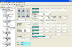
Fortunately, when a few flow conditions are known accurately, an algorithm can be found that can model the behavior of a given control valve for the whole flow range. Expert sizing software leads the user through a sequence of data input steps, which allows for the calculation of this algorithm. Expert sizing software will be the topic of a more in-depth article on valve sizing and selection in the June 2013 issue of Flow Control magazine. For now, here are 5 Control Valve Selection Points Every Processor Should Consider:
1. Optimal Travel: When a valve is sized correctly, the range of operation will correspond well to the control range of the valve. Travel at normal flow should fall within 50 to 70 percent opening angle. Travel at maximum flow should fall below 90 percent. Travel for minimum flows should be above 20 percent open to avoid erosion of the trim.
2. 1/2 The Pipeline Size Rule: Because rotary valves typically have more Cv than rising stem valves, it’s not uncommon to have a control valve smaller than the pipe size. To avoid valve damage caused by piping stresses, the valve size should not be less than half of the diameter of the pipeline. When the valve size that best fits the flow conditions is smaller than half of the pipeline, consider reduced capacity trim rather than a smaller valve.
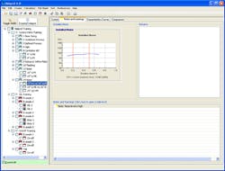
3. Installed Gain Curve: The installed gain curve indicates how the control valve will perform under the given process conditions. A high gain means small changes in valve position will produce large changes in flow, therefore casing the process to overshoot. Low gain means large changes in valve position will produce small changes in flow, causing the process to behave sluggishly.
A constant gain line at 1.0 within the control range would be ideal. For best results, gain should be between 0.5 to 3.0, and the ratio of maximum to minimum gain should be ≤ 2.0.
4. Flow Velocity & Erosion: Erosion damage is closely tied to the velocity of the media. This damage is typically seen first on your valve trim, but can also affect the body and downstream piping. The erosion damage is only amplified with the presence of particulate (erosive media), or flashing conditions.
Maintaining a proper velocity, especially when the media is erosive or flashing, is important for extending your valve life.
• Try to maintain opening angles greater than 20 percent open on all flow conditions.
• On clean service maintain velocities lower than 37 ft/sec (32 ft/sec for butterfly valves).
• If media is erosive or flashing moving to a larger valve should be considered as the added surface area will help minimize erosion
5. Noise: Aerodynamic noise (noise generated from gases or steam) is strongly related to exit velocity of the media. The concern is mechanical damage of the valve assembly with aerodynamic noise, damage of valve, actuator, or accessory components from intense vibration. Government regulations typically limit noise to 85 dBA if a person will be near the noise source for eight hours or more, however it’s unrealistic to think every valve will perform to that noise level. Keep noise levels below 110 dBA to prevent mechanical damage to your assembly.
Hydrodynamic noise is used to predict cavitation intensity. Manufacturers often have different opinions about cavitation, however it’s also accepted that if you want to eliminate damage you must lower noise down to an acceptable level (which in turn means lowering the intensity of the cavitation). For specific noise recommendations please review your specific valve sizing software for noise levels applicable to your specific size valve.
Steven Hocurscak has an engineering degree from WPI University, and has worked with Metso for the past seven years. His current role with Metso is the North American Business Manager for the metal-seated product line. Mr. Hocurscak can be reached at [email protected].


