In many fluid pumping applications a mechanical throttling device — typically a valve — is used to limit or control flow. Although valves are a common and effective means of control, they waste both mechanical and electrical energy.
In contrast, variable frequency devices (VFDs) increasingly offer a more attractive solution in today’s industrial, commercial and residential building applications because of their ability to control motor speed (read: flow or pressure) and stability with finer degrees of precision. VFDs that feature dynamic active energy control algorithms not only reduce power consumption, but also often introduce additional opportunities for achieving higher efficiency and cost savings through smarter and smaller system architecture and improved performance.
This article introduces the core concepts necessary for understanding the potential gains of VFDs when used instead of a valve to control pumping and other fluid processing applications. It discusses how to choose pump and speed control equipment for greater energy and system efficiencies and identifies some of the best features to assure that new equipment investments quickly pay for themselves.
Be proactive on efficiency by getting predictive with affinity laws
A set of three standard rules, known as the affinity laws, help determine optimal system performance settings for centrifugal loads, usually pumps and fans. These laws generally define the core relationships between elements of the pump system and the speed of the motor driving the pump.
The three affinity laws are:
- Flow or volume varies linearly with speed.
- Pressure or head varies as a square of the speed.
- Power or energy consumption varies as a cube of the speed.
The affinity laws are often used to describe what flow will occur at specific pressure settings within the system. Calculations are represented as system curve graphs that facilitate visualizations of the critical factors.
Two additional elements of the pump system are required to draw a system curve graph. These are:
- Static head or lift — the height that the fluid must be lifted from the source to the outlet
- Friction head — the power required to overcome flow-dependent and nonlinear losses caused by the flow of fluid in the piping, valves, bends and other devices
The information from system curve graphs can be used to determine a system’s appropriate load requirements and potential energy savings. As such, the system curve graphs are also critical to selecting the best pump for a given system or application.
When selecting a pump, consider the maximum flow rate required in gallons per minute, as well as the feet of pressure the pump should develop. Then, determine a pump and impeller size capable of meeting the maximum required flow within a reasonable amount of buffer. Rarely does a pumping application require the pump to produce maximum flow. The system curve and the pump performance curve will intersect at the desired operating point of pressure and flow.
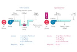
Here is where the system architecture and equipment choices begin to make a significant difference: When valve control is added to the basic system curve, the operating point of the pump curve shifts. This is because a throttled system curve adjusts based on the amount of horsepower required to achieve flow at full speed.
Essentially, throttled systems create mechanical stresses — excessive pressure and temperature — on the pump system, which can cause premature seal or bearing failures. More important, these systems also consume tremendous amounts of energy.
In valve-controlled architectures, power relates directly to the flow speed. In contrast, VFDs allow for mediation between the amount of flow, the motor speed and the energy used to control the overall pump system.
Affinity laws: Pump flow is proportionally linear to motor speed, whereas energy consumption is a cubic relationship.
VFDs provide optimal speed control for more efficient flow
Applying a VFD to the pump allows greater control of the pump’s speed electrically while using the actual energy required to produce a given flow.
For example, the power consumption of a valve-controlled system might reach 60 percent at 20 percent of flow, but when a VFD is employed, power consumption may only rise to 20 percent at roughly 60 percent of flow. This marks a dramatic savings in power because the measures are literally inversed.
These power savings are because VFDs rely on advanced algorithms to dynamically alter the frequency of the alternating-current motor, such that speed, flow and energy consumption can be effectively and efficiently reduced in the system. Put another way, VFDs allow the pump motor to perform at reduced speed, significantly lowering the operating point.
However, they can also stabilize and maintain the pump motor performance at that optimally reduced speed point. To accomplish this task, today’s advanced VFDs feature active energy control — dynamic, energy-optimizing algorithms — that determine the ideal output voltages based on the reference frequency and real-time parameters of the motor.
The active energy control algorithm is built into the logic of the drive and activated by default. Upon start-up of the VFD, the algorithm initially sets the drive output voltage at the same level as the motor voltage based on the linear volts per hertz (V/Hz) method for the same reference frequency. It then begins to reduce the voltage incrementally to optimize energy usage.
The algorithm monitors several real-time parameters of the motor to prevent the motor from entering conditions that may lead to instability. When the motor enters the optimal zone of operation, the drive output voltage stays at the same level until there is a change. Commands to the drive, such as a change in the reference frequency or a change in other real-time parameters, trigger dynamic voltage adjustments. Once the output voltage stabilizes, the drive monitors the real-time parameters of the motor to maintain efficiency.
Additional cost savings through VFD selection
Using active energy control, the VFD’s flow control ultimately improves the efficiency of the motor and the application, providing superior energy savings.
Because VFDs with dynamic V/Hz control methods also ensure the stability of the motor, they provide additional cost savings. In these applications, VFDs with active energy control can help reduce pressure, which helps limit mechanical stresses that can cause wear and tear on equipment over time.
Consider the following example: Testing of the active energy control algorithm was performed at a wastewater treatment plant in which a VFD drove a centrifugal pump. The motor and the VFD were rated at 50 Hz for this particular installation. The VFD input power was taken for both linear V/Hz mode and the active energy control mode for 25 Hz, 30 Hz, 40 Hz, 45 Hz and 50 Hz. Savings over linear V/Hz mode was observed ranging from roughly 18 percent at 25 Hz to 4 percent at 50 Hz. Compared with standard drives, the VFDs with active energy control can typically achieve a 2 to 10 percent return on energy savings.
However, some VFDs may also be packaged with additional energy-saving features, such as a kilowatt (kW) meter for power monitoring and an onboard energy savings calculator that can be used to capture cost savings proactively. Users configure their currency type, local energy cost in that currency and the format of the energy savings to be displayed. After setting these parameters, the drive monitors and logs the instantaneous kW every 15 minutes. This data can be displayed on the keypad or pulled through a communication protocol to show the actual savings in a cumulative, daily average, monthly average and yearly average format.
Finally, VFD-controlled systems provide additional cost reductions over valve-controlled systems through the elimination of components and valve losses. Valve-controlled systems require additional piping to bring the valve to a height at which it can be adjusted. VFDs eliminate this piping and reduce valve losses caused by bends or additional piping.
With the reduction of these losses, smaller pumps and impellers can often be used with lower losses. This minimizes the system footprint and results in a substantial system cost reduction and installation savings, further economically justifying the use of the VFDs.
Conclusion
The use of VFDs for dynamic speed control in pumping and other fluid processing applications offers many advantages over traditional valve-controlled systems. VFDs generally improve process performance and reduce maintenance costs. They are designed to optimize energy use, distinguishing them from different approaches among manufacturers. To provide optimal total system cost reductions from VFDs and further increase system efficiency and performance, talk with a high-quality vendor that can help determine the most strategic implementation for the application.
Charles Tahara is global product manager for Industrial Drives, Eaton, with 11 years of experience as a customer or manufacturer of industrial control products. For more information, visit eaton.com/drives.


