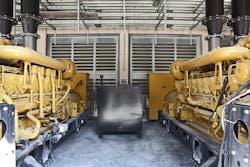
A group of multiuse office towers was going up in downtown Manhattan. The construction design of the buildings included eight 2-megawatt diesel generators to act as a backup power supply to the multibuilding complex in case of a power outage. The main fuel tanks were located in the cellar and would pump up fuel to the day tanks located above the generators as needed. Seven generators were enough to provide the needed power to all buildings with the eighth acting as backup, but they were designed for all to be able to provide power in unison.
"Unfortunately, they didn’t all work. The last two in the linear setup were starving for fuel and wouldn‘t run," said Remon Yussif, PE, LEED AP, CEM, CPMP, the commissioning manager for Jacobs — Global Buildings Consulting, who was brought in to commission the generators. Jacobs Engineering Group Inc. is an international engineering, architecture and construction firm that offers support to industrial, commercial and government clients across multiple markets.
Identifying the source
"We knew what the problem was, now we had to find out what caused it," said Paul Liesman, Jacobs’ director of commissioning. "We sat down with the client and his engineering team and we agreed right away that it was a flow problem. The next step was to identify the cause and find a solution.
"Renowned engineer W. Edwards Denning famously said, ‘You can’t manage what you can’t measure’ and that is certainly true with fluids. We had experiences with commissioning challenges like this before and decided to call in an ultrasonic flowmeter company to provide metering services that would give us the data we needed to identify the source of the problem. Liesman selected a flowmeter manufacturer he worked with before that provided non-invasive meters that clamp onto the pipe, eliminating the need to cut into the pipe and intrude with the flow.
FLEXIM ultrasonic meters clamp directly onto the pipe and can detect the presence of particulates and air bubbles. Photo courtesy of FLEXIM.
How ultrasonic flowmeters work
"One of the major benefits of ultrasonic flowmeters is that, unlike traditional meters, they contain no moving parts and do not need frequent calibration and maintenance," explained Izzy Rivera, FLEXIM America’s product engineer. "Measurements are made using the transit time difference method. It exploits the fact that the transmission speed of an ultrasonic signal depends on the flow velocity of the carrier medium. An ultrasonic signal moves slower against the flow direction of the medium and faster when it is in the flow direction.
"For the measurement, two ultrasonic pulses are sent through the medium, one in the flow direction and the second against it. The meter’s transducers work alternately as transmitter and receiver. The transit time of the signal sent in the flow direction is shorter than that of the signal sent against the flow. The meter measures the transit time difference and calculates the average flow velocity. Since the ultrasound signals propagate in solids, the meter can be mounted directly onto the exterior of the pipe non-invasively." Rivera’s company has replaced troublesome transducer paste with solid mounting pads that do not need periodic replacing and conform to the shape of the pipe.
Measuring the flow
Reyes Hernandez, a field service engineer for FLEXIM, arrived three days later and met with the client’s engineers and the commissioning team from Jacobs.
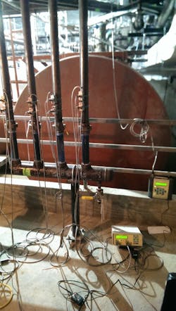
"After examining the generators, fuel tanks and piping on the fourth floor and in the cellar with the other engineers," said Hernandez, "we decided on the installation of 15 two-channel portable flowmeters and 30 sets of transducers at key data acquisition points on the piping on the fourth floor and in the cellar."
The meters were delivered in two days and were placed so they could identify the volume flow rate entering and leaving the generators and at other key points.
"Meters and cables were strewn all around the generator room," Hernandez said. "It was like putting EKG wires on a patient, only the patient was very large."
Identifying the culprits
After the measurements were taken, Hernandez was able to make his assessment.
"We started up all eight generators and measured all of the lines simultaneously and averaged the flow rates," he said. "The required flow rate to the generators was supposed to be 3.5 gallons per minute (gpm). Our readings on the supply lines came in at an average of 2.3 gpm. Generator eight was particularly heavily affected and began to choke out like it was coughing."
Air in the fuel
Hernandez was able to assess from the meters’ diagnostics that there were gas bubbles in the fuel. The meter has an aeration detector so it detects from outside the pipe if air or gas bubbles are in the liquid. "It works similar to how a car’s headlights are dimmed by fog as the fog scatters the light," he said. "We use sound waves to measure liquid flows and if air bubbles are present in the liquid, they cause the sound to scatter. The sound intensity to the receiver is affected and is detected by the meter and identified by an algorithm that looks for these affects.
"When we went to the sight glass at the fuel filter/separator, there were so many air bubbles that it looked like a fish tank."
In addition to this problem, the issue of the main storage tanks and the piping that fed the day tanks lingered.
"Downstairs there were aeration issues also," said Hernandez. "Our readings indicated that three of the four supply pipes from the storage tanks were heavily aerated and most of the fuel oil flowed through the fourth."
A particulant problem
But that wasn’t all.
"We determined through our metering data that all of the fuel lines were clogged with debris," Hernandez said. "Evidently, the subcontractor who installed the piping had failed to brush down the interior of the pipe while [he was] installing it. So when the fuel oil was installed, it mixed with the left-behind welding material and it all came together. When we ran the pump that moved fuel oil from the cellar to the day tanks, it choked out and made a loud noise. If we hadn’t turned it off it would have burned out. Then we turned it off and waited about 30 seconds, ran it, and it did the same thing — run between 15 and 30 seconds max and then it would choke out."
Jacobs had a two-way filter so work could be done on one filter without interrupting the flow. Technicians opened up the foot valve and found the screen clogged with debris. They cleaned it out and ran the pump again, and again it choked out. They opened it up once more and the filter was clogged with debris again. In all, they spent a day to remove the foot valve from the tank. Because of the flow readings, they decided to remove and inspect the piping. Once they did it was evident that the entire piping system needed to be cleaned out or replaced.
Rust and water issues existed as well. "Generators create a negative pressure in the fuel supply manifold and if there are small air leaks, air and/or moisture will be added to the system," Yussif said.
The Jacobs team used the meter readings to specifically identify the problems. They found air and water leaks in the system and assisted the engineer of record to find all of the problems.
The Jacobs team worked with the meter manufacturer to prepare a complete report for the client that included information needed to redesign certain aspects of the generator system. "Although it ended up being a big project, it could have been much worse," Yussif said. "There was no damage to the pumps or the generators and downtime was significantly reduced."
Jack Sine is a freelance writer specializing in environmental issues and the chemical, power and HVACR industries. He can be reached at [email protected] or by phone at 845-831-6578. For more information on ultrasonic flow measurement, visit flexim.com.


