(a.k.a. "The Pump Guy")
Hello Pump Guy,
I work in maintenance at a rendering plant. We have many centrifugal pumps on site for moving industrial water and treated water (boilers, cookers and cooling towers). Other than maintenance history records, we have no information on our pumps. The nameplates are illegible, scratched or abraded-off. Nobody here knows where to find the performance curves. We get no help from the local pump distributor.
You wrote recently that the pump head is determined by the impeller diameter and speed. How can I use the impeller size and RPM to determine the head and probable performance curve? Any help you can offer is greatly appreciated.
Thanks,
Valiant S.
###
Hello Valiant,
I had the occasion recently to read the instructions on a bottle of shampoo. The instructions said, Lather! Rinse! Repeat! That’s all!
The instructions didn’t say my hair should be wet before applying the shampoo. The instructions didn’t say how much shampoo I should use. The instructions didn’t indicate how long I should leave the shampoo in my hair before rinsing, or how many times I should repeat the process. The shampoo manufacturer assumes too much regarding the users.
The pump industry also assumes too much regarding the users. There are certain things the pump industry knows, but doesn’t often verbalize. So let’s verbalize the assumed rules of pumps.
There are three families of centrifugal pumps. The largest family is the classic centrifugal water pump because water is (and always has been) the most popular liquid transported in bulk with a pump.
The classic centrifugal water pump has a radial-flow impeller and generates all head by centrifugal action. This pump is excellent for pumping all liquids that flow approximately like water. This family represents about 75 percent of all centrifugal pumps.
Most centrifugal pumps are directly coupled to an electric motor. In the U.S., the most popular electric motor is the 4-pole motor on 60-Hz electricity. This motor rotates at 1,800 RPM. When coupled to a pump in a pipe system filled with liquid, the motor and pump rotate at about 1,750 RPM.
Before going further, let’s define some terms:
- “Head” is a measure of energy. The units are “feet of head.” Head is converted into pressure for water by dividing feet of head by 2.31. If the liquid is not water, specific gravity (density relative to water) is factored into the conversion.
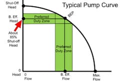
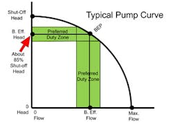
- “Shut-off Head” is the beginning of all pump curves. It represents maximum head at zero flow.
- “Best Efficiency” is the optimum combination of head and flow through the pump at the least energy consumption.
- “BEP” is Best Efficiency Point, the head (feet) and flow (GPM) coordinates of best efficiency.
- “Best Efficiency Zone” is approximately 90 percent to 110 percent of BEP. Also called the preferred duty zone or the “sweet spot” on the performance curve.
The first rarely verbalized assumption is: “On a 4-pole industrial electric motor, the pump impeller diameter in inches, multiplied by itself or squared, is the approximate “shut-off head” of the pump in feet.
This means that a standard centrifugal pump with a 6” impeller on a 4-pole motor (60-Hz electricity) will generate 34 to 38 feet of shut-off head (6 x 6 = 36). Likewise, a 9” impeller on a 4-pole motor would generate about 80 to 82 feet of shut-off head (9 x 9 = 81). And a 13” impeller would generate about 170 feet of shut-off head.
On interpreting numerous different pump curves, you will see these numbers are accurate within about 5 percent.
The second rarely verbalized assumption is: The best efficiency point (BEP) for water pumps with radial flow impellers is about 85 percent of the shut-off head. The actual BEP can vary from 82 percent to 88 percent of the shut-off head depending on design specifics.
The third rarely verbalized assumption is: The pump should be operated at, or close to, the best efficiency point on the performance curve. Most pump companies don’t give instructions explaining what the operator or process engineer must do to control and hold the pump to Best Efficiency.
I liberally used the words “about” and “approximately” many times in the previous paragraphs. The unwritten assumptions are not precise like mathematics. The assumptions include variables depending on the pump design, the impeller design, impeller surface finish, blade count, liquid viscosity, internal clearances, and the actual motor speed. The assumptions don’t apply to pumps with mixed-flow or axial-flow impellers, special-duty pumps, or PD pumps. However, the assumptions cover about 75 percent of all centrifugal pumps in a rendering plant.
If your motor speeds or impeller diameters are different, then we can apply the Affinity Laws. The Affinity Laws are covered in other Pump Guy articles in Flow Control magazine (“Cheat Sheets: The Affinity Laws,” Flow Control, 2007, flwctrl.com/pg_affinitylaws).
Now, let’s use this information and develop a probable performance curve for your pumps.
Figure 1 shows the important elements of a typical centrifugal pump curve with a radial-flow impeller. The vertical axis reports head or elevation in feet starting at 0 feet and rising to shut-off head. Notice that best efficiency head is about 85 percent of the shut-off head. The horizontal axis reads flow in gallons per minute (GPM) starting at 0 GPM rising through best efficiency flow and proceeds to maximum flow at zero head.
Out on the curve is a point called BEP (Best Efficiency Point) with coordinates drawn to best efficiency head in feet, and best efficiency flow in GPM. In green, around the best efficiency head and flow, is the preferred duty zone or “Sweet Spot.” This zone is where the pump is happy with minimal running vibrations, minimum heat generation and noise, and minimum component distortion.
Let’s say one of your pumps has a 9” impeller and is directly coupled to a 4-pole electric motor. The shut-off head would be approximately 81 feet (92 = 81). The best efficiency head of this pump would be about 69 or 70 feet (85 percent of 81 feet).
This pump would be good for a pipe system that contains about 70 feet of resistance. Or, this pump can generate about 30 PSI of water pressure.
How do you know if a pump is performing as it should? I often discussed the importance of instrumentation in pumping systems.
Let’s say you have a water pump with an 8” impeller spinning on a 4-pole electric motor. The shut-off head would be about 64 feet. Best efficiency head would be about 54 feet. Ambient water at 54 feet would convert into 23 PSI differential pressure.
Install a pressure gauge on the pump suction nozzle and on the discharge nozzle. Open the valves, turn on the pump, and allow the flow to stabilize. If the differential pressure across the pump is somewhere between 21 PSI and 25 PSI, this pump is somewhere in the preferred duty zone and close to best efficiency.
Who would have thought you could start with the speed and diameter of a pump impeller and develop a valid performance curve? You can use this information to develop your own performance curves.
It also shows how proper instrumentation contributes to pump reliability. Pumps need working gauges. Most pumps can be controlled to best efficiency by interpreting either differential pressure gauges or a flowmeter. The pump is stressed when the differential pressure (or flow) varies from the projected readings.
I hope this information helps. As you purchase new pumps, be sure to keep an original performance curve. Nowadays, you can download many curves direct from your pump company website.
Stay in touch,
Larry Bachus (“The Pump Guy”)
The Pump Guy Seminar will be in Indianapolis, June 16-18, 2015. Contact Matt Migliore at [email protected] for details.
Larry Bachus, founder of pump services firm Bachus Company Inc., is a regular contributor to Flow Control magazine. He is a pump consultant, lecturer, and inventor based in Nashville, Tenn. Mr. Bachus is a retired member of ASME and lectures in both English and Spanish. He can be reached at [email protected].


