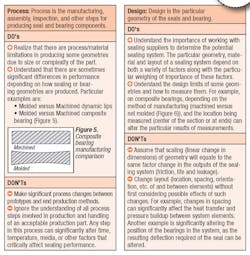
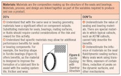
Validation is a crucial part of the design process of sealing systems. It is required to ensure the system performs as desired, is reliable as expected, and provides the confidence that the performance and reliability will both be maintained over the life of the process. Validation is not just a series of tests; it is a process. In the August issue of Flow Control (pages 16-20), Part I of this two-part article on the seal validation process discussed Validation Process Flow and DO’s and DON’Ts in the areas of Pressure, Load, Speed, Dynamics, and Temperature. Part II, published here, will further explain how to use the Process Flow effectively, cover DO’s and DON’Ts in the areas of Time, Assembly, Media, Process, Design, and Materials, and discuss what happens when a “DON’T” is done.
Using the Process Flow Effectively
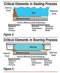
In order to successfully use the validation process to validate components and thus sealing systems, some critical level of knowledge of the elements affecting the sealing system (seals, bearings, wipers, and other components used to ensure sealing success) is needed. Here are some steps that can be used well in the validation process:
- Determine how to best validate each component.
- Determine the criteria for success/failure.
- Compile a list of activities and criteria.
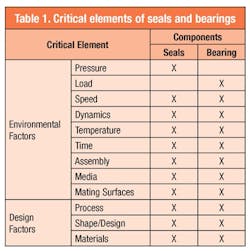
Between seals and bearings, the critical elements are summarized in Table 1. The major difference is that pressure is associated with seals, while load is associated more typically with bearings.
If understanding or knowledge of any of the factors noted in Table 1 is not adequate, then the risks of the process not providing a robust plan and subsequent validation results increase. If help is required, end-users should consult a seal provider to address any issues early to avoid delays and lessen the risk of frustration and shortcuts downstream during the validation testing.
What Happens When A ‘DON’T’ Is Done?
The validation process can be difficult in light of the number of steps involved prior to any testing. Each step along this process usually possesses a number of assumptions, and this uncertainty combined with limited time and money for validation can create many potential pitfalls to avoid. In many cases, it is possible that one of the unknowns or assumptions associated in the process will result in a “DON’T” being done. When this happens, one needs to be aware of potential negative results from the validation process, such as:
- Learning nothing
- Misinterpreting results
Learning Nothing: Although it may be difficult to believe that nothing productive (i.e., “learn nothing”) can come from something (testing), this is a somewhat common occurrence. A typical example would be testing a system for sealing performance and experiencing auxiliary component failure, such as in a belt, piston rod, or bushing. Failure of the seal may be experienced, but there would be considerable questions about the cause — whether the seal failed due to being exposed to conditions outside of what it was designed for or because the seal itself was the root cause. Testing is done, but little or no value in validating sealing performance results.
Another example is testing in which all sealing systems pass or all fail. The testing either pushes too hard or not hard enough to show a difference. Once again, testing is done, but nothing is learned.
Misinterpreting Results: Misinterpretation of results from validation testing is a fairly common occurrence, especially if testing is based on one of the following practices:
Designing a test that introduces artificial failure modes. An example, from a sealing perceptive, is lifecycle testing — trying to accelerate the number of cycles within a shortened period of time. This potentially would produce high-frequency, cycling conditions well beyond what the seal could ever experience in the field. The high frequency significantly changes the formation of a fluid film under the seal, which is needed for friction, wear and life. This can lead to excessive fluid film, which shows up as leakage, or the other extreme of insufficient lubrication, which creates premature wear and higher friction. It also can create the potential for the wear particles not to be removed, adding further to wear and limiting life.
Designing a test that does not test the right failure modes. A good example to highlight this situation is dynamic low-temperature testing of polyurethane u-cups. The objective is to understand the friction, leakage and wear performance at extreme low temperature as it was identified as a potential failure mode. However, in testing, the need to drop the temperature quickly and hold for a period of time causes the surrounding humidity to form ice on the shaft (Figure 7).
During startup at low temperature, the ice is allowed to impact the u-cup, causing considerable damage, which is misidentified as wear and leakage due to low temperatures. Other components in the system would eliminate the ice chunks from contacting the u-cup in a properly designed sealing system for this behavior, but in this case, the introduction of a set of environmental conditions, which the u-cup itself is not going to see in the real application, introduced an incorrect failure mode for friction, wear and life.
Not running enough testing to ensure reliable data. Confidence in the validation testing is important. However, there are variables in running system validation that cannot be controlled, such as contamination type, amount of exposure to contamination, or ambient temperatures. These variables can have an effect on seal and bearing performance. In some literature, up to 67 factors have been identified that would affect sealing performance. Slight changes in those factors have an effect on sealing performance. Therefore, the need to avoid a “one and done” scenario (testing once only), should be avoided. If not, then an apparent pass in one situation may have a potential to be a failure in another. Enough testing needs to be done to ensure reliability.
Not accepting an adequate level of variation between tests results for each test. Again, confidence in the validation testing is important. As mentioned before, the massive amount of variables and combinations of variables involved inevitably introduces noise, which cannot be controlled in a cost-effective manner, so one needs to accept that some variation is likely to occur. For example, it is not uncommon to find leakage results that vary up to an order of magnitude. As a rule of thumb, any variation in test results around or greater than 100 percent should be examined to ensure that the testing procedure and setup are appropriately matched for the application and that any results are not the results of an aberration.
Often, control systems, measurement devices, delays in testing due to equipment maintenance or repair, careless or uneducated handling of components, or other unintentional activities can significantly influence the results of a test. Care should be taken to ensure that all tests can be repeatable, as economically possible, and that all involved are communicating well to help eliminate or identify early potential issues for large variation between results. One should be prepared to accept a range of measurements when defining success from sealing system validation.
Both of these potential paths (learning nothing or misinterpreting results) could end with one of the two outcomes that no one wants — redevelopment or a faulty launch. In either case, this equates to more human resources, more machine time, more money, and more time lost.
Larry Castleman is technical director of Product Development for Trelleborg Sealing Solutions. Mr. Castleman has held a variety of engineering positions related to manufacturing and marketing in 20 years with Trelleborg Sealing Solutions. Mr. Castleman can be reached at larry.castle [email protected].
Martin Franz is product development engineer for Trelleborg Sealing Solutions. Mr. Franz has been working in the seal industry for 14 years in a variety of capacities. Mr. Franz can be reached at [email protected].
John McLaughlin is manager of product testing for Trelleborg Sealing Solutions. He has more than 15 years of experience in product testing of polymer base products. Mr. McLaughlin can be reached at [email protected].
Mark Sitko is product development engineer for Trelleborg Sealing Solutions. Mr. Sitko has been with Trelleborg Sealing Solutions in a variety of engineering positions for the last 13 years. He has a total of 16 years of experience in the sealing industry. Mr. Sitko can be reached at [email protected].
REFERENCES
1. B. Gupta and L. Castleman, “Viscoelastic Effect on the Performance of Elasotmeric and Plastic Seals by FEA,” Proceedings of the 51st National Conference on Fluid Power, March 12-14, 2008.
2. H. Jordan, “Alternative Surfaces (Coatings and Treatment) in Hydraulic Cylinders,” Proceedings of 12 International Sealing Conference, September 2002.

