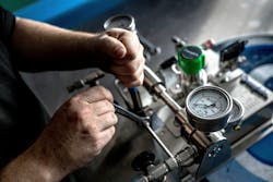
Many laboratories, test centers and industrial sites are tasked with doing more with fewer resources. This approach can lead to gas distribution systems being left undermaintained and vulnerable to inefficiencies. In addition, as experts retire or relocate, they take valuable knowledge with them, leaving gaps in training and best practices for managing systems.
These challenges may lead to facilities encountering inefficient gas bottle usage or undetected leaks, either of which can raise costs if they go unresolved. Other times, facilities may have difficulty diagnosing problems when they do not have reliable line drawing maps of their distribution systems. Furthermore, when facilities must repeat tests or when they encounter inaccurate results, the outcomes are often untimely setbacks or costly delays.
Avoiding these issues is critical for lab and reliability managers, engineers and operations staff. Therefore, optimizing the integrity of gas distribution systems is vital to the safe and efficient delivery of gas throughout their labs or plants (Figure 1).
Many companies benefit from the trained eye of a professional consultant who can identify areas for improvement by reevaluating gas panels from the ground up. Often, a new perspective can reveal overlooked trouble spots and open new conversations beyond “the way it has always been done.”
Given the operational challenges plants and refineries face related to staffing and maintenance, a variety of solutions can help plant managers solve real-world problems. These solutions present new opportunities to create safe and efficient performance while reducing gas losses caused by previously undetected leaks (Figure 2).
Setting benchmarks
Professional pressure control advisory services can provide critical analysis to identify system upgrades, inform pressure regulator sizing and selection, and guide the design and assembly of engineered solutions (Figure 3).
Third-party field engineering professionals will start by evaluating and documenting the current state of the gas distribution system, looking at both the holistic view and the details to create benchmarks to compare against as the team monitors progress.
A professional who is familiar with specific gas delivery challenges can offer:
- Suggestions for how existing systems can be modified to meet new requirements rather than starting from scratch.
- Options for easy procurement of gas panels built and tested by experienced, certified technicians to help reduce time, cost and the risk of on-site assembly errors by less-practiced installers.
- An unbiased recommendation that puts the needs of your operation and application first.
An advisor can also help ensure that toxic and flammable gases are delivered safely with minimal loss, that panels provide clear instruction and that systems are easy to operate and troubleshoot.
The knowledge that comes from working with global engineering professionals provides new opportunities for cost improvements, as well as greater control over the safety and efficiency of the gas distribution process.
Understanding pressure regulation subsystems
Beyond understanding leaks and issues within a gas distribution system, facilities need to implement fixes that will simplify maintenance and ensure efficient gas delivery. This critical step involves optimizing a system to work best for the specific needs of the facility.
Gas distribution systems are built around one or a series of pressure regulation steps and are typically composed of four subsystems:
Source inlet
The source inlet (Figure 4) connects the high-pressure gas source to the gas distribution system. Importantly, the inlet must be built with appropriate cylinder connections, hoses, tubing, filters, vent, purge and relief functions. Some gas panels may not include a standard source inlet, so always verify componentry and confirm that panels will use the correct cylinder connector. Some high-pressure and/or hazardous gases (including oxygen) also require the use of special application hoses.
Primary gas pressure control
The primary gas pressure control (Figure 5) completes the first pressure reduction and ensures the source gas is delivered at the correct flow rate to the next stage of the system. The reduction is accomplished with either a single pressure regulator or via a dual pressure regulator arrangement. Pinpointing correct inlet and delivery pressures is challenging. It is important, for example, to factor for differences between media, such as ammonia that is bottled around 116 psi (8 bar) and nitrogen that can be bottled at 4351 psi (300 bar). Meanwhile, many bottles that use a two-stage pressure regulator may not, in fact, require one. This can be a cost-saving opportunity.
Automatic changeover
The automatic changeover (Figure 6) seamlessly switches from one gas source to another to ensure an uninterrupted supply. This is performed through staggered set points of two pressure regulators, allowing the system to continue to operate as the primary gas source is changed. It is advisable to look for a solution that allows for varying changeover pressures to get the most use from gas bottles.
Point-of-use module
The point-of-use module (Figure 7) provides the critical last stage of control. Typically having a pressure regulator, gauge, and isolation valve, this subsystem gives operators a convenient and accurate method for adjusting pressure. Where varying line pressure between the primary gas pressure control and point-of-use is acceptable, a single-stage pressure regulator might be used to reduce cost and complexity.
Simplifying operations and maintenance
Panel design can have a great impact on the safety, serviceability and efficiency of operating gas distribution systems. Not all systems are created the same. At times, panels can lack important features that simplify operations and maintenance, while reducing the potential for leaks.
One way to optimize a system is to standardize the panels and operation instructions, including using interchangeable parts wherever possible. This helps ensure that operators become well-versed in the panels, reducing maintenance time.
From a design standpoint, using compression fittings in place of threaded connections can help minimize the time required to access components for maintenance – that is, individual parts are easy to remove in-line while leaving others in place. This creates the flexibility to change components rather than replace panels and helps technicians work efficiently. It also reduces the risk of fittings experiencing thread damage when unscrewing and reinstalling a relief valve, for instance.
As you are tasked with doing more with fewer resources, you could be missing cost savings opportunities within your gas distribution system. To maximize your investment, consider working with an advisor to help you identify opportunities for improvement.
Matt Dixon is senior principal design engineer for Swagelok Company.


